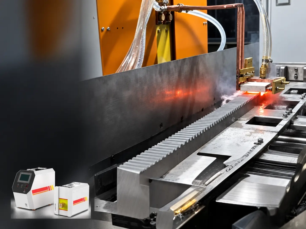
Gear Rack Induction Hardening Machine for Machine Tools & Industrial Automation
Ⅰ. Gear Rack Induction Hardening in Operation
Gear Rack Induction Hardening
Localized Induction Hardening of Rack Teeth
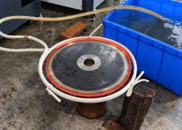
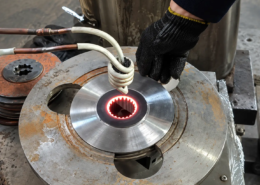
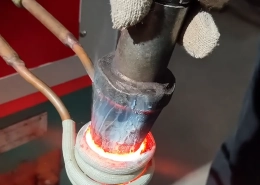
In the process shown above, the induction coil is positioned close to the rack teeth and heats the required tooth area. The heated region is then quenched according to the hardening process.
For longer treatment lengths, relative movement between the gear rack and the inductor can carry the heating zone along the rack.
The process is developed around the area specified for hardening rather than treating the entire rack as one uniformly heated workpiece.
Ⅱ. What Areas of a Gear Rack Can Be Hardened?
The required hardened area depends on the rack design and heat-treatment specification.
A rack tooth includes the tooth tip, flank and root, but these areas should not automatically be assumed to require the same hardness pattern or case depth. Some applications may call for hardening mainly around the working tooth surface, while others may specify a different hardened-zone profile.
The required area should therefore be identified on the drawing before the inductor and process are selected.
Material and prior condition also matter. The rack material must be suitable for the required induction-hardening response.
For an initial process evaluation, the most useful information is usually the rack drawing, material and a marked hardened zone.
Ⅲ. Inductor Positioning and Scanning Along the Rack Teeth
Gear racks differ from smooth shafts because the induction coil works around a repeated tooth profile rather than a continuous cylindrical surface.
The inductor does not necessarily follow every detail of the tooth shape. Its geometry and position are developed according to the rack profile and the required heating pattern.
Important considerations include the tooth geometry, module, rack section, coil-to-tooth relationship and available clearance around the treatment area.
For a long rack, the treatment can be carried along the rack length by controlled relative movement between the workpiece and the inductor. During this movement, the relationship between the coil and the teeth should remain sufficiently controlled for the required process.
Long workpieces may also need appropriate support and guidance so that the rack position does not change excessively as the treatment progresses.
A change in module, tooth form or rack section can require different tooling even when the overall rack length is similar.
Ⅳ. Quenching and the Final Hardened Result
Heating alone does not define the final hardened zone. The heated rack teeth must also be quenched according to the required process.
On a moving or scanning setup, the quenching arrangement has to work with the heated area as the treatment progresses. Depending on the application, quenching may be incorporated into the induction tooling or provided through a separate spray arrangement.
The visible heating pattern should not be used as the sole measure of the final result. Acceptance should follow the heat-treatment specification, which may include surface hardness, hardened-zone location and case depth where specified.
Required case depth is considered together with material, tooth geometry, heating method and quenching when the process is developed.
Ⅴ. Machine Configuration for Gear Rack Hardening
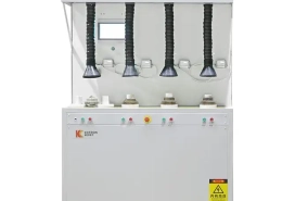
A gear rack induction hardening machine is normally configured from the rack geometry and production requirement rather than from rack length or power rating alone.
A system may include:
The exact layout depends on the workpiece and treatment requirement.
A long rack requiring hardening over an extended length may need guided movement and additional support. A shorter rack, or a component requiring only one localized hardened area, may use a different handling arrangement.
Related rack sizes may sometimes share the same power platform while using different inductors, fixtures or process settings. This has to be evaluated from the actual workpieces rather than assumed from nominal dimensions.
Ⅵ. Applications in Machine Tools and Industrial Automation
Induction-hardened gear racks are used where rack teeth are exposed to repeated contact and wear in rack-and-pinion drive systems.
Typical application areas may include:
In machine tools and gantry systems, long gear racks may be used to transmit motion over extended travel distances. Automation equipment can also use rack-and-pinion drives where linear movement is required.
The hardening requirement still has to be defined from the actual rack drawing. Rack dimensions, tooth geometry, material and required hardened zone can differ substantially between applications.
Ⅶ. Information Required for Machine Selection
A gear rack drawing provides more useful information for machine selection than a request based only on power or operating frequency.
| Information | Why It Matters |
|---|---|
| Gear rack drawing | Shows tooth form, rack section and overall geometry |
| Material | Helps evaluate the expected hardening response |
| Rack length | Affects support and movement requirements |
| Tooth geometry / module | Influences inductor and tooling development |
| Required hardened area | Defines where heating and quenching are needed |
| Target hardness, if specified | Defines the required surface result |
| Case depth, if specified | Helps define the hardening requirement |
| Production requirement | Influences handling and automation configuration |
If the hardened area has already been defined, marking it directly on the drawing is particularly useful.
For an initial discussion, however, a clear drawing or photo, the material if known, and the area that needs to be hardened are usually enough to begin the evaluation.
Based on this information, the induction coil, rack positioning, heating and quenching method, power supply and machine configuration can be reviewed for the application.
Ⅷ. Frequently Asked Questions
Click a question to expand the answer.
What information do I need to provide for an evaluation?
A rack drawing, the material if known, and the area that needs to be hardened are usually enough to begin. Target hardness, case depth and production requirement can be added if they are already defined.
Do all areas of the rack tooth need the same hardness?
Not automatically. The tooth tip, flank and root should not be assumed to require the same hardness pattern or case depth. The required area is identified on the drawing before the inductor and process are selected.
Is a gear rack hardened the same way as a smooth shaft?
No. A rack has a repeated tooth profile rather than a continuous cylindrical surface, so the inductor geometry and position are developed around the tooth profile and the required heating pattern.
How are long racks treated?
The treatment is carried along the rack by controlled relative movement between the workpiece and the inductor. Long racks may also need support and guidance so the rack position stays stable as the treatment progresses.
Can related rack sizes share the same machine or power supply?
Sometimes. Related rack sizes may share the same power platform while using different inductors, fixtures or process settings, but this has to be evaluated from the actual workpieces rather than assumed from nominal dimensions.