
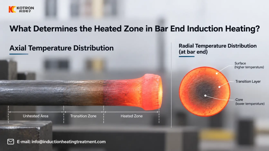
What Determines the Heated Zone in Bar End Induction Heating?
Coil design, bar size, frequency, heating time and positioning all affect where the heat develops before forging
In bar end induction heating, reaching forging temperature is only part of the process. The heated length, temperature transition along the bar and temperature difference through the cross-section all affect how the material behaves during the following forming operation.
The visible red-hot area gives a useful indication, but it does not show the complete temperature distribution inside the workpiece.
2. Coil Design Sets the Basic Shape
3. Insertion Depth and Bar Position
4. Frequency and Bar Diameter
5. More Power Doesn’t Improve Uniformity
6. Radial and Axial Temperature Uniformity
7. Change Parameters or Change the Coil?
8. Start With the Section Being Formed
Ⅰ. The Visible Red Zone Is Not the Whole Heating Zone
When a heated steel bar leaves the induction coil, the glowing section shows where the surface temperature is relatively high. It does not directly show the temperature at the center of the bar.
Induced current is generally more concentrated toward the surface, while penetration depth depends on operating frequency and material properties. Thermal conduction then helps reduce the temperature difference between the hotter outer region and the core.
Heat also moves along the length of the bar. A hot end transfers heat into the adjacent, cooler section, creating a transition zone beyond the area most strongly coupled to the coil.
For this reason:
Visible heated length ≠ exact coil length ≠ complete internal temperature profile
For forging, the useful question is whether the section that will actually deform has reached the required thermal condition.
Ⅱ. Coil Design Sets the Basic Shape of the Heated Zone
The inductor has a strong influence on where energy is concentrated.
Its geometry, length, diameter, number of turns, turn spacing and position relative to the bar all affect electromagnetic coupling.
For bar end heating, this matters because the required hot zone usually has a defined starting and ending position.
If the coil effectively couples with a section longer than the forming process requires, simply reducing power may lower the temperature without correcting the basic shape of the heated zone.
The required heated length should therefore be considered when the inductor is designed.
A bar with the same diameter but a different forging length may need a different coil or positioning arrangement.
Ⅲ. Insertion Depth and Bar Position Must Be Repeatable
Coil design alone does not determine the result. The workpiece has to return to the same position from cycle to cycle.
If one bar is inserted farther into the inductor than another, the axial position of the hot zone can shift.
Poor centering can also change the coupling between the workpiece and different sides of the coil.
For batch production, mechanical stops, fixtures or automatic positioning can improve insertion-depth repeatability.
This is why the heating station and the workpiece-handling method should be considered together. A correctly designed inductor cannot fully compensate for inconsistent positioning.
Ⅳ. Frequency and Bar Diameter Affect Surface-to-Core Heating
Bar diameter becomes increasingly important when through-heating is required.
Operating frequency affects how deeply electromagnetic energy penetrates into the workpiece. The temperature inside the section then continues to develop through a combination of direct induction heating and thermal conduction.
With a larger cross-section, the outer region may reach a high temperature while the center still needs additional heating time.
This does not mean that bar diameter alone determines the correct frequency.
Frequency selection also depends on:
•Material
•Required heated length
•Heating time
•Target temperature
•Coil design
•Required production rate
Two bars that need a similar final forging temperature may still require different frequency and heating-cycle settings.
Ⅴ. More Power Does Not Automatically Improve Temperature Uniformity
Increasing induction power can shorten the heating cycle, but it does not necessarily improve the temperature distribution through the bar.
If energy is applied too aggressively for the selected frequency, bar size and heating time, the surface can reach a high temperature before the center reaches the required condition.
Extending the heating cycle gives more time for temperature differences through the section to decrease, but an unnecessarily long cycle also increases heat loss and keeps the material at elevated temperature for longer.
Power and heating time therefore need to be adjusted together.
A useful process is not simply the fastest cycle the power supply can produce. It is a cycle that gives the required temperature profile before the workpiece moves to forming.
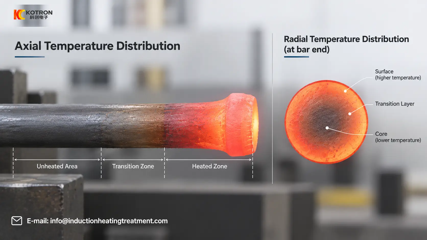
Ⅵ. Temperature Uniformity Has Both Radial and Axial Directions
For bar end heating, “uniform temperature” can refer to more than one thing.
Radial Temperature Distribution
This is the temperature difference from the surface toward the center of the bar.
For thicker workpieces, a surface temperature reading does not necessarily describe the thermal condition of the core.
This becomes important when the following forging operation requires deformation through a substantial part of the cross-section.
Axial Temperature Distribution
This is the temperature profile along the length of the bar.
The very end, the main forming zone, the transition region and the cold section of the bar may all have different temperatures.
Some forming operations need a relatively broad hot section. Others require a much more concentrated end-heating zone.
The correct axial profile is therefore defined by the forming process, not by how long the bar appears red after heating.
Ⅶ. Should You Change the Parameters or Change the Coil?
When the heating pattern is wrong, changing the power setting is often the easiest first adjustment. It is not always the correct one.
A simple troubleshooting approach is:
| Heating Result | Check First |
|---|---|
| Heated zone consistently too long or too short | Coil geometry and insertion depth |
| Heated position shifts between workpieces | Positioning, fixture or feeding repeatability |
| Heated zone is correct but temperature is too low | Power and heating time |
| Surface becomes hot while the core remains insufficiently heated | Frequency, heating time and bar diameter |
| One side heats differently from the other | Bar centering and coil-to-workpiece relationship |
| Required hot zone cannot be obtained after reasonable parameter adjustment | Inductor design and workpiece positioning |
These are starting points rather than fixed diagnoses. Several variables may affect the same heating pattern.
Observing where the problem occurs is more useful than changing several settings at the same time.
Ⅷ. Start With the Section That Will Actually Be Formed
Before selecting power or designing the induction coil, define the part of the workpiece that needs to deform.
A drawing with the required heated section marked on it provides a clearer starting point than the total bar diameter and length alone.
For bar end induction heating, the main process inputs are:
•Workpiece material
•Bar diameter
•Required heated length
•Target temperature
•Production cycle
•Following forging or forming operation
From these conditions, the coil geometry, positioning, operating frequency, power and heating time can be evaluated as one heating process.
A useful heating cycle produces the required temperature profile in the section that will actually be formed.
Key Takeaway
The heated zone in bar end induction heating is set by coil design, bar size, frequency, heating time and positioning working together — not by power alone. Before adjusting parameters or ordering an inductor, define the section that will actually be formed, and evaluate the complete temperature profile both across and along the bar.
Frequently Asked Questions
Click a question to expand the answer.
Why doesn’t the red-hot area show the complete temperature distribution?
The glowing section shows where the surface is relatively hot, not the temperature at the center of the bar. Heat also moves along the bar length, so the actual heated zone extends beyond the visible red area into a transition zone.
What should I check first if the heated zone is consistently too long or too short?
Start with coil geometry and insertion depth. The inductor’s length, diameter and position define the basic shape of the heated zone, so adjusting power alone may not correct it.
Does more induction power improve temperature uniformity?
Not necessarily. Too much power for the selected frequency and bar size can overheat the surface before the center reaches temperature. Power and heating time should be adjusted together.
What information do you need to design a bar end heating setup?
Workpiece material, bar diameter, required heated length, target temperature, production cycle and the following forging or forming operation. The coil geometry, positioning, frequency, power and heating time are then evaluated together.
Need a Bar End Heating Machine?
Send your bar drawing and mark the heated section. We will evaluate the coil, frequency, power and heating cycle for your forging process.


