
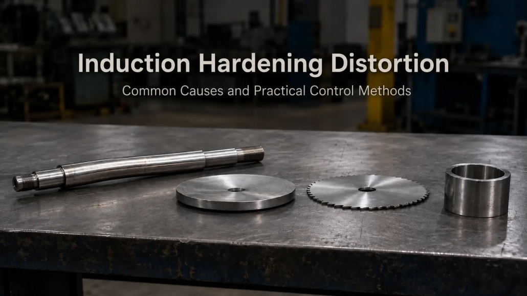
Induction Hardening Distortion: Common Causes and Practical Ways to Reduce It
A shaft comes out bent. A bore becomes smaller. A thin plate develops waves before quenching has even started.
These are different forms of induction hardening distortion, and they do not have the same cause or the same fix.
Heating distribution matters, but so do workpiece restraint, coil position, spray alignment, part geometry and the way the component is supported during scanning. Quenching conditions can also change the final distortion and residual stress state. A published study on a full-float truck axle shaft, for example, examined how different quenching rates affected both distortion and residual stresses during induction hardening. See the study in the Journal of Materials Engineering and Performance.
For production troubleshooting, it is usually more useful to look at the type of distortion first and then work backward through the process.
| 1. Common Distortion Types | 2. Saw Blade Case: 500 × 3 mm |
| 3. Long Shafts: Restraint & Alignment | 4. Plate & Strip Parts |
| 5. Bore Shrinkage & Compensation | 6. What to Check First |
| 7. The Whole-Process View |
1. Common Forms of Distortion After Induction Hardening
Depending on the part, dimensional changes may appear as:
• Bending of shafts and other slender components
• Warping of strips and plate-shaped parts
• Bore expansion, shrinkage or taper
• Deflection of disc-shaped parts
• Changes in ball screw pitch
• Other local dimensional changes associated with the hardened area
Even parts made from similar steel can behave differently because geometry changes the way heat flows through the workpiece and how the material is allowed to expand.
Research on induction-hardened AISI 4340 discs also shows that distortion is connected with more than the heating recipe alone. In that study, the initial material hardness affected both hardening depth and the amount of distortion. The paper is available through the National Research Council Canada.
The examples below deal with several problems commonly encountered in actual hardening work.
2. A 500 mm × 3 mm Saw Blade That Warped During Heating
Thin parts can distort before the quench starts.
One production example involved a woodworking saw blade measuring 500 mm × 3 mm, with its teeth hardened by high-frequency induction heating.
During heating, the blade developed irregular wave-like distortion. The thin section was highly sensitive to local temperature differences, and thermal stress caused the blade to twist out of shape.
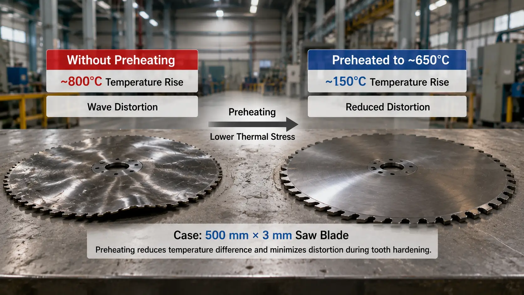
The process was changed by preheating the blade in a conventional furnace to approximately 650°C before the induction stage.
Previously, the local induction-heated area had to undergo a temperature rise of roughly 800°C. After preheating, the remaining temperature increase during induction heating was only about 150°C.
The temperature difference in the blade became much smaller, thermal stress was reduced, and the irregular distortion no longer prevented the tooth-hardening operation from being completed.
The number 650°C should not be copied as a general preheating specification for thin parts. It belongs to this particular example. Material, dimensions, previous heat treatment and the required hardening result all have to be considered before using a similar process.
What the example does show is that reducing induction power is not the only response to heating distortion. Sometimes the larger problem is the temperature gradient already being created in the workpiece.
3. Long Shafts: Do Not Restrain Thermal Expansion Too Tightly
Long, slender shafts are particularly sensitive during scanning hardening.
As the heated zone moves along the shaft, the workpiece expands. If both ends are held too rigidly, this expansion is restricted and additional stress is introduced into the part.
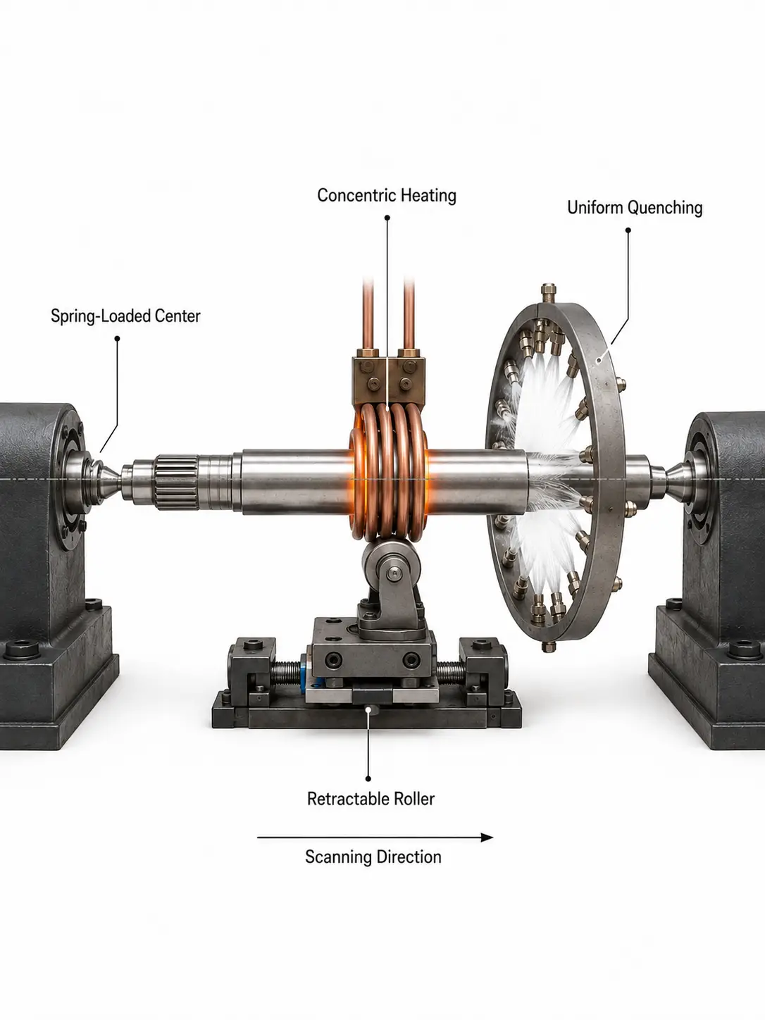
One practical solution is to loosen the upper center or use a spring-loaded or pneumatic center. Another arrangement is to allow one end of the shaft to move axially as the workpiece becomes longer during heating.
The fixture still has to locate the shaft correctly. It simply should not prevent normal thermal expansion.
Very slender shafts may need additional support. Correcting rollers can be installed in a way similar to a steady rest on a lathe. As the inductor reaches the support position, the roller moves out of the way and then returns after the inductor has passed.
Alignment deserves just as much attention.
If the effective coil is closer to one side of the shaft, heating around the circumference will not be uniform. The same problem occurs if the quenching spray is off-center. One side then experiences a different cooling condition from the other.
Keeping the inductor, quenching unit and shaft as concentric as practical helps reduce this difference.
When a scanning-hardened shaft bends, changing power or scan speed is therefore not always the first thing to try. Check the centers, shaft support, coil position and spray position as well.
4. Plate and Strip Parts: Single-Side Hardening Can Pull the Part Out of Shape
Single-side hardening of a strip or plate often produces a concave-type deformation.
The temperature field through the thickness is not symmetrical. The hardened side goes through concentrated heating and subsequent cooling while the opposite side experiences a different thermal cycle.
Where the part specification permits it, symmetrical hardening of both sides can reduce this imbalance.
In some applications, heating has also been applied to the opposite surface while the required side is being hardened. The intention is to reduce the temperature difference through the part, not to replace the induction process itself.
Another shop-floor method is pre-bending.
If trial production shows that a component consistently becomes concave after hardening, the untreated part can first be given a controlled convex shape. Part of the hardening distortion then compensates for the initial pre-bend.
This approach has been used in surface hardening of steel rails.
It only makes sense when the deformation is reasonably repeatable. If one part bends 1 mm in one direction and the next behaves completely differently, pre-bending is unlikely to be the real solution.
5. Bore Shrinkage: Sometimes the Process Can Be Compensated Rather Than “Corrected”
Bore distortion needs to be treated differently from shaft bending.
Consider internal hardening of a cylinder liner.
In the example described here, the outer wall is water cooled while the inner surface is hardened. After hardening, the internal diameter becomes smaller. The dimensional change associated with the hardened structure cannot develop freely toward the outside, so the bore is affected instead.
If repeated production shows that this shrinkage is stable, it can be taken into account before hardening.
The bore is machined slightly larger in the previous operation, leaving enough dimensional allowance for the expected shrinkage. After hardening, the subsequent grinding operation brings the bore to its final size.
The same principle can be considered for full-tooth hardening of internal gears when the dimensional change follows a predictable pattern.
This is not the same as ignoring distortion.
It is process compensation. It works because the dimensional change is known in advance and repeats within an acceptable range.
6. A Few Things Worth Checking Before Changing the Recipe
When the same part starts showing excessive distortion, first look at whether anything mechanical has changed.
☐ Is the shaft still free to expand?
☐ Has a center been tightened differently?
☐ Is the inductor still centered?
☐ Is the spray ring in the same position?
☐ Are the nozzles delivering evenly?
☐ Does a slender section have enough support?
Then look at the distortion itself.
If every part bends in roughly the same direction and by a similar amount, the process may have a systematic dimensional change that can be reduced or compensated.
If the deformation changes noticeably from part to part, look harder for instability in positioning, support, heating or cooling before adding a fixed dimensional correction.
Part geometry also sets practical limits. A 3 mm thick saw blade, a solid transmission shaft and an internally hardened cylinder cannot be expected to respond to the same hardening strategy.
7. Distortion Control Starts with the Whole Process
Induction hardening distortion cannot usually be traced to one number on the power supply.
For a slender shaft, the problem may start with restraint or poor concentricity. With a plate, asymmetric heating may dominate. Bore shrinkage may be regular enough to compensate during machining. A very thin part may need its temperature distribution changed before normal induction hardening can be carried out successfully.
Heating parameters still matter, as do scanning speed and quenching conditions. But they sit inside a larger mechanical and thermal process.
That is why a useful distortion investigation should include the workpiece, fixture, inductor, movement and quenching system, not just the heating power.
Key Takeaway
Induction hardening distortion is not one problem with one fix. Bending, warping and bore shrinkage each trace back to a different part of the process — restraint, asymmetric heating, or a repeatable dimensional change. Identify the distortion type first, then check the mechanical setup before touching power or scan speed.
Frequently Asked Questions
Why does a long shaft bend during scanning induction hardening?
Can bore shrinkage after induction hardening be corrected?
Does preheating reduce distortion in thin parts?
What should I check first when distortion suddenly increases?
Need Help Controlling Distortion in Your Induction Hardening Process?
Tell us your part geometry and current setup. We will help you pinpoint the likely source of distortion and the practical change that reduces it.


