
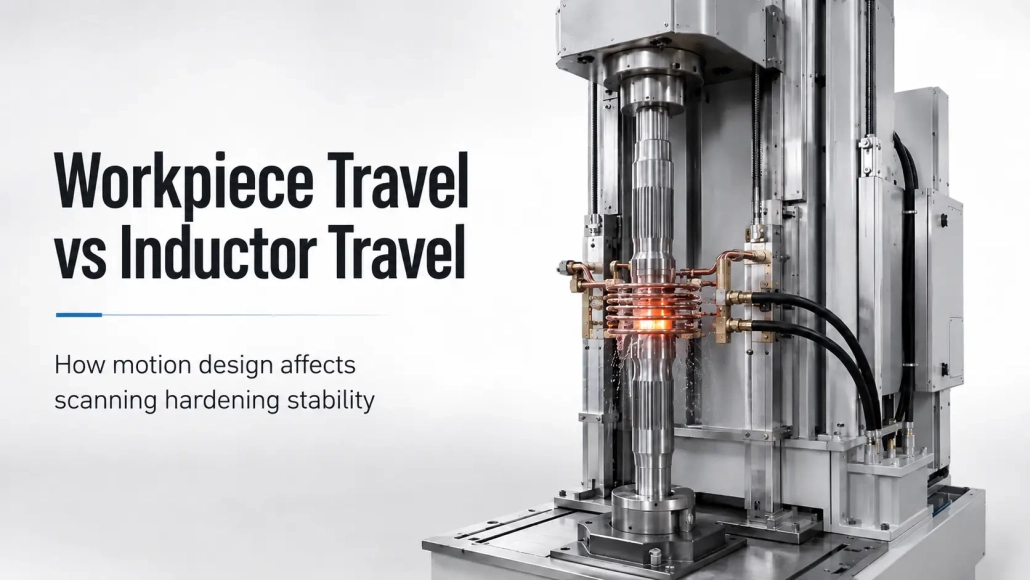
Why Some Induction Hardening Machines Move the Workpiece — While Others Move the Inductor
In scanning induction hardening, relative movement has to be created between the workpiece and the induction coil. At first glance, the choice seems simple: either move the part or move the inductor.
In practice, that decision affects the height of the machine, moving mass, vibration, positioning accuracy and the type of workpiece the machine can handle.
A short shaft and a 6 m diameter gear obviously should not use the same motion arrangement. Even two long workpieces may require different solutions if one can rotate smoothly while the other creates excessive vibration.
For this reason, motion design in an induction hardening machine is not simply a question of which drive system is faster. The more important question is:
Which part of the system should move, and can that movement remain stable throughout the hardening stroke?
1. Two Basic Motion Arrangements in Scanning Hardening
For general scanning hardening machines, two arrangements are commonly used.
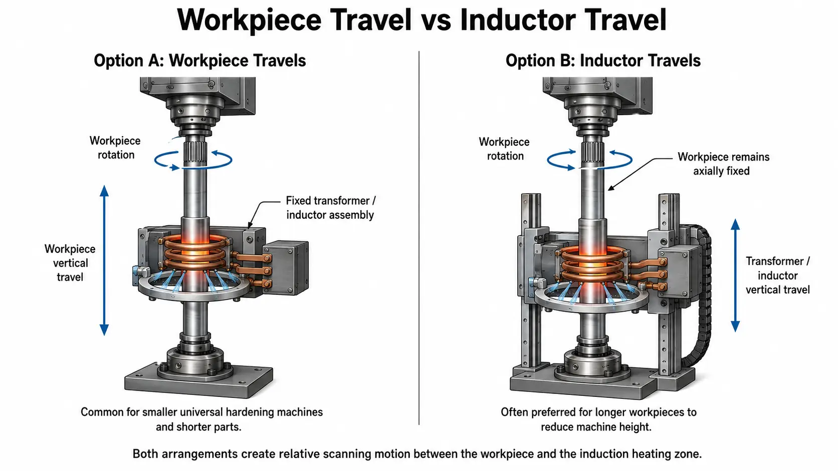
In the first, the workpiece rotates and also moves in the scanning direction, while the transformer and inductor remain in a fixed position.
In the second, the workpiece rotates but does not travel axially, while the transformer and inductor assembly moves along the workpiece.
Both arrangements create the same basic relative motion required for scanning hardening. The difference is where the moving mass is located.
This difference becomes increasingly important as the workpiece becomes longer, heavier or more difficult to support.
Small universal hardening machines, camshaft hardening machines, axle-shaft machines and steering-rack hardening machines often use workpiece travel together with rotation. For longer components, moving the transformer and inductor assembly can become more practical.
2. Why Workpiece Length Can Decide What Moves
Machine height is one of the first factors to consider.
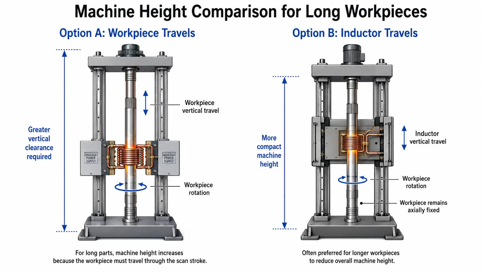
If a long workpiece itself has to move vertically through the hardening zone, the machine needs enough space for the component both before and after the scan.
According to the machine-design practice in the supplied technical material, a scanning hardening machine using workpiece travel may require a total height of more than approximately twice the scanning length.
When the transformer and inductor assembly moves instead, the required total machine height can be closer to slightly more than one scanning length.
This difference becomes significant with long shafts.
For this reason, the source material gives around 2 m workpiece length as a practical point beyond which vertical machines generally tend to use transformer/inductor travel rather than moving the workpiece through the full scanning stroke.
This should be understood as an engineering practice described in the source material rather than a universal dimensional rule for every machine.
The principle is more important than the exact number:
The longer the workpiece, the more machine space is required if the workpiece itself performs the scanning movement.
Moving the smaller induction assembly can reduce overall machine height considerably.
3. Heavy Workpieces Often Favor Inductor Movement
Weight introduces another problem.
Consider a large gear being hardened tooth by tooth. The source material gives an example of a gear approximately 6 m in diameter and 20 t in weight.
Trying to move such a workpiece through the scanning stroke would require a very large mechanical structure.
The transformer and induction coil are much smaller and lighter than the gear. In this case, moving the heating assembly is naturally the more convenient arrangement.
The same reasoning can apply to other very heavy components.
When the workpiece is already difficult to support and rotate, adding another large linear movement to the workpiece side increases the mechanical requirements of the machine.
This does not mean that “the heavier component should always remain stationary.” It simply means that moving mass is an important part of the design decision.
4. But Moving the Lighter Component Is Not Always Better
There are exceptions.
Roll hardening is a good example.
A roll can be both long and heavy, which would seem to favor moving the transformer and inductor assembly. According to the supplied material, however, the transformer/inductor assembly used for some roll hardening applications can itself be relatively heavy and can generate considerable vibration during operation.
In this situation, fixing the transformer and inductor while moving the workpiece may provide better process stability.
This example shows why equipment design cannot be reduced to a simple rule such as:
“Move whichever component is lighter.”
The real question is whether the moving system can maintain stable motion at the required speed and stroke.
A lighter assembly that vibrates significantly may produce a less stable scanning condition than a heavier workpiece moving on a well-supported mechanical system.
5. Hydraulic or Mechanical Drive: Which Is More Stable?
The motion arrangement determines what moves. The transmission system determines how it moves.
The supplied machine information divides general hardening-machine drive systems broadly into hydraulic and fully mechanical types.
Hydraulic transmission has several practical advantages. The structure can be relatively simple, driving force is high, and travel speed can be fast. The source material notes movement speeds above 150 mm/s in suitable systems.
Its weakness is motion control.
Hydraulic systems can have less stable travel speed and lower positioning accuracy. For induction scanning hardening, where heating conditions are closely related to scanning speed, this can become an important limitation.
The source material therefore describes hydraulic-driven induction hardening machines as becoming less favored.
Fully mechanical systems may use several drive arrangements, including:
• T-type lead screws
• Ball screws
• Linear guide-based movement systems
Their main advantage is more stable travel and higher positioning accuracy. Mechanical systems also make controlled changes in movement speed easier to implement.
For applications where scanning speed and positioning repeatability are important, this gives the mechanical arrangement a clear advantage.
However, it would still be misleading to say that one component such as a ball screw automatically guarantees a stable hardening process.
Transmission accuracy is only one part of total machine stability.
6. Slide-Type and Column-Type Machine Structures
The mechanical structure supporting the moving system also matters.
The supplied material divides common movement structures into slide-type and column-type designs.
Slide-Type Structure
The slide-type structure has been widely used in general induction hardening machines.
The machine bed is typically a cast or welded structure that has undergone stress relief or aging treatment. This gives it relatively high load capacity and good structural stability.
Its main advantages are:
• high load capacity
• good stability
• suitability for large and heavy workpieces
• wide application range
The trade-off is weight and mechanical complexity.
A heavy machine bed is less flexible to move or integrate, while slideways and guide surfaces can require more complicated machining.
For machines intended to carry heavier workpieces or maintain stability over demanding operating conditions, however, that mass and rigidity can be useful.
Column-Type Structure
Column-type machines use a lighter supporting structure and are more common in some European and North American machine layouts.
Their advantages include lower machine weight and more flexible movement. They can also make it easier to integrate the machine structure with the quenching-liquid circulation and cooling system.
The limitation appears when the workpiece becomes large or the stroke becomes long.
The supplied material notes that column-type structures are less suitable for very large or heavy parts, and that stability can decrease over long travel distances, for example through workpiece vibration.
This is another reminder that a machine that moves easily is not automatically the machine with the best stability.
7. So Which Arrangement Is More Stable?
There is no single answer that applies to every induction hardening machine.
If the question is only about drive consistency and positioning, the supplied material clearly favors fully mechanical transmission over hydraulic transmission for stable scanning and accurate positioning.
But whole-machine stability depends on more than the drive.
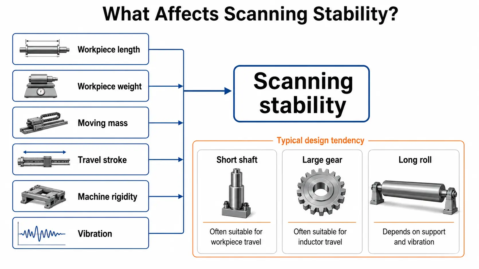
The design has to consider:
workpiece length + workpiece weight + moving mass + travel stroke + machine rigidity + transformer/inductor weight + vibration
A short shaft can be efficiently rotated and moved through a fixed induction station.
A long vertical shaft may be better hardened with a moving transformer and inductor so that the machine does not need excessive height.
A very large gear naturally favors movement of the relatively small induction assembly.
A long roll may appear to favor the same solution, yet vibration of a heavy transformer/inductor assembly can reverse the decision.
That is why motion design should be evaluated as part of the complete hardening process rather than selected from a standard mechanical formula.
8. The Best Motion System Is the One That Keeps the Scan Stable
In scanning induction hardening, movement directly affects the heating process.
If scanning speed changes unexpectedly, the heating time received by each section of the workpiece changes as well. Positioning error can also shift the hardened zone away from its intended location.
For this reason, the best mechanical arrangement is not necessarily the fastest or lightest one.
It is the arrangement that can maintain the required scanning movement with sufficient rigidity, repeatability and stability for the actual workpiece.
For a universal induction hardening machine, that choice starts with a few basic questions:
• How long is the part?
• How heavy is it?
• Which component is easier to move?
• How much travel is required?
• Will the moving assembly remain stable over the complete stroke?
Once those questions are answered, the choice between workpiece travel and inductor travel becomes much clearer.
Key Takeaway
The decision to move the workpiece or the inductor is not made by speed or weight alone. Workpiece length controls machine height — a part that moves itself needs roughly twice its scan length of clearance, which is why long shafts favor a moving transformer/inductor. Workpiece weight and vibration then decide whether the lighter assembly is actually the more stable choice. Fully mechanical drives generally beat hydraulic drives on scanning stability and positioning, but the whole machine’s rigidity — slide-type or column-type — matters just as much. The right arrangement is the one that keeps scan speed and position stable over the full stroke for the actual part.
Frequently Asked Questions
1.Which is more common — moving the workpiece or moving the inductor in scanning hardening?
Both are widely used. Workpiece travel with rotation is common on smaller universal, camshaft, axle-shaft and steering-rack machines, while transformer/inductor travel becomes more practical as the workpiece gets longer or heavier.
2.At what workpiece length do machines typically switch to moving the inductor?
The source material gives around 2 m workpiece length as a practical point beyond which vertical machines tend to move the transformer/inductor rather than the workpiece. This is an engineering guideline, not a universal rule — the principle is that a workpiece that moves itself needs roughly twice its scanning length of machine height.
3.Is hydraulic or mechanical drive better for scanning hardening?
For stable scanning speed and accurate positioning, fully mechanical drives — lead screws, ball screws and linear guides — are generally favored. Hydraulic drives can be fast and simple but offer less stable travel speed and lower positioning accuracy, which matters because heating depends directly on scan speed.
4.Why would a machine move the heavy workpiece instead of the lighter inductor?
Because a lighter assembly that vibrates significantly can produce a less stable scan than a heavier workpiece moving on a rigid, well-supported system. Roll hardening is one example where vibration of a heavy transformer/inductor assembly can reverse the usual decision.
Not Sure Which Motion Arrangement Fits Your Part?
Tell us your workpiece length, weight and hardening requirements, and we will help you choose the most stable scanning configuration.


