
Angular Groove Hub Bearing Induction Hardening: Inductor Selection & Power Supply Guide
Angular groove hub bearing induction hardening presents a unique challenge: the bearing’s sloped (angular) groove surfaces are asymmetric, making uniform heating far more difficult than on a flat or cylindrical surface. Get the inductor design wrong, and you’ll see uneven case depth — too shallow at the groove center, too deep on one side. Get it right, and you’ll hold a tight hardness window across both grooves with minimal parameter tweaking. This guide compares the two inductor configurations that dominate production and helps you pick the right one for your line.
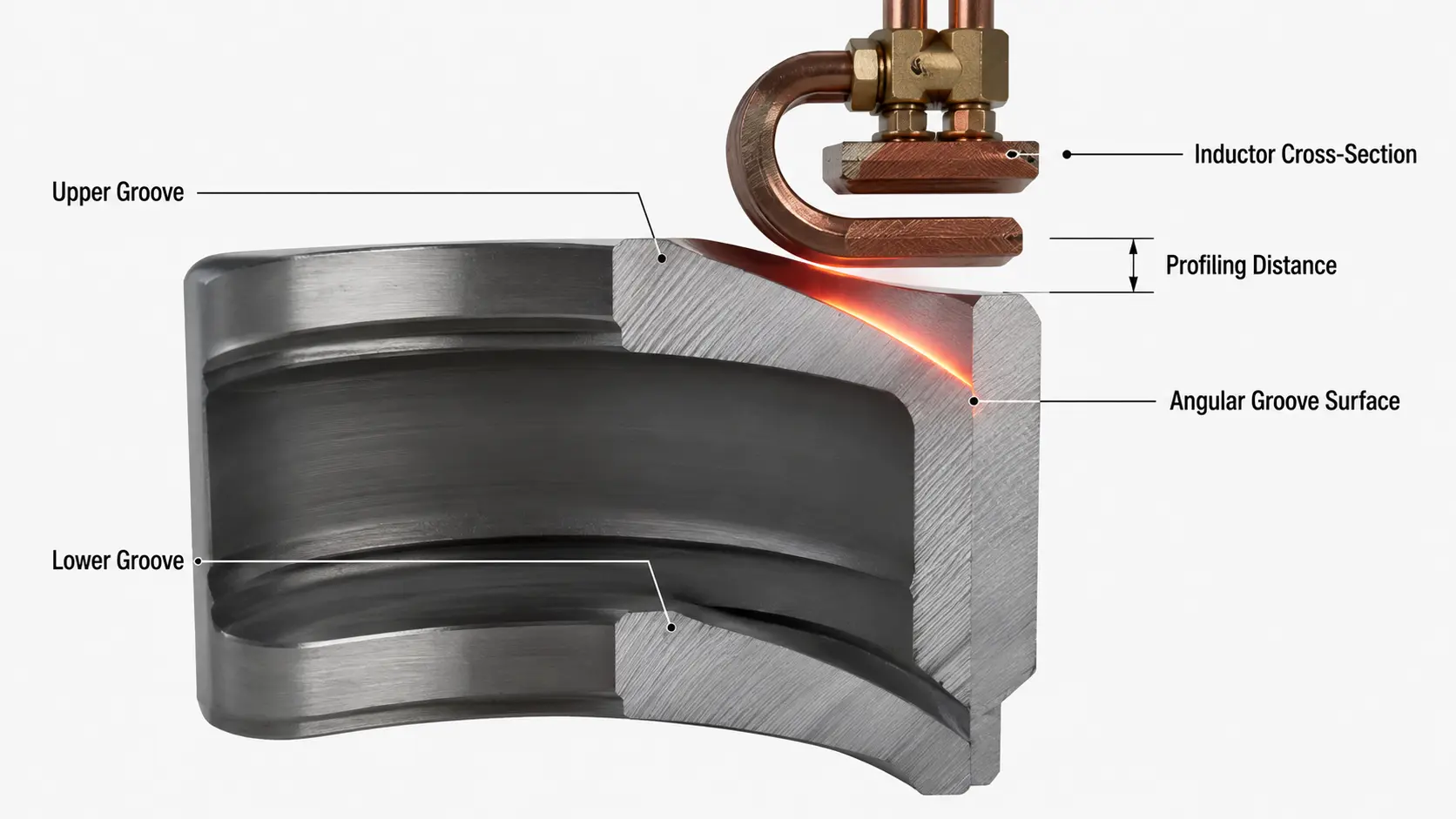
Table of Contents
1. Why Angular Grooves Are Harder to Harden
Ordinary bearing rings have flat or simple cylindrical raceways. Induction heating is straightforward: a coil wraps around or sits inside the part, and the magnetic field distributes cleanly across the target surface.
Angular groove hub bearings are different. The groove surfaces are sloped at an angle relative to the bearing axis, and the upper and lower grooves are asymmetric — they sit at different axial positions and face different directions. This means:
- A standard cylindrical inductor cannot heat both grooves evenly
- The magnetic field coupling distance varies across the sloped surface, causing uneven heat distribution
- The second groove is always harder to heat consistently because the inductor’s position must be readjusted
These challenges exist regardless of bearing size — but they become more pronounced as the angular surface gets larger. Bearing manufacturers use materials like GCr15 (100Cr6) bearing steel, with case depth typically specified at 1.5–3.5 mm and hardness at 58–62 HRC. The bearing steel grades and hardening requirements are well standardized; the challenge is entirely about delivering heat where it’s needed.
2. Approach 1: Single-Turn Profiled Inductor — Two Steps, High Efficiency
How It Works
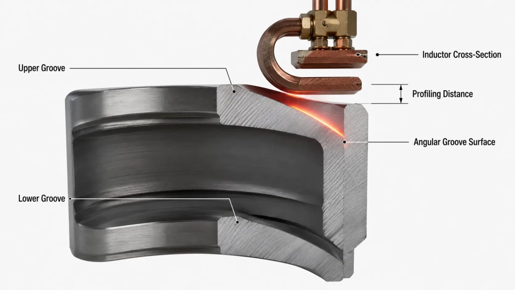
A single-turn copper inductor is machined with a contour that closely matches (profiles) the angular surface of one groove. The first groove is hardened, then the inductor is repositioned — adjusting height and heating parameters — and the second groove is processed. Think of it as a precision tool that hugs the workpiece: close fit, high energy transfer.
What Makes It Work Well
Heating efficiency is the standout advantage. Because the inductor profile follows the groove geometry closely, the magnetic field coupling distance is minimized — meaning more energy goes into the workpiece and less is wasted. For induction heating power supply selection, this translates to a lower power requirement for the same case depth, or deeper hardening at the same power level.
Where It Can Go Wrong
The main pain point is the second groove. Since the upper and lower grooves are positioned asymmetrically, the inductor height and heating parameters must be readjusted each time. For bearings with large angular surfaces, two specific defects can appear:
- Shallow center: insufficient case depth at the midpoint of the groove, where the magnetic field coupling is weakest
- One-sided depth: excessive case depth on one side of the groove, caused by uneven profiling distance
The fixes: adjust the profiling distance between inductor and workpiece in the opposite direction (reverse profiling) to compensate for thermal asymmetry. If that doesn’t resolve it, switch from a single-turn to a two-turn (double-loop) inductor — the second turn redistributes current flow, evening out the heating pattern. This is similar in principle to techniques discussed in our guide to shaft induction hardening challenges, where inductor profiling distance is also the primary lever for case depth control.
3. Approach 2: U-Shaped Inductor — Single Shot, Both Grooves at Once
How It Works
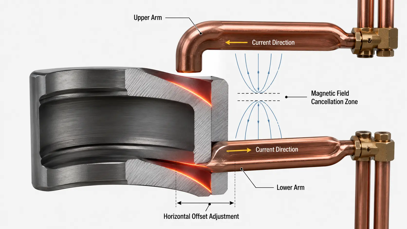
The inductor is shaped as a horizontal U-shaped half-loop. In one heating cycle, both angular grooves are hardened simultaneously. The hardening machine must have horizontal offset (translation) capability to align the inductor precisely with both groove surfaces.
The Efficiency Trade-Off
The U-shaped design has a built-in physical limitation: the current in the upper and lower arms flows in opposite directions. This means their magnetic fields partially cancel each other out, reducing the net heating effect on the workpiece. The result is lower heating efficiency compared to the single-turn profiled approach.
In practice, this means you’ll need a higher-power power supply to achieve the same case depth, or accept a slightly longer heating cycle. Refer to induction heating frequency classifications to ensure your power supply — typically super-audio frequency (10–40 kHz) for bearing applications — can deliver sufficient power density for the U-shaped configuration.
The Precision Risk
Horizontal offset is the critical parameter here. If the translation is set incorrectly, the inductor can make physical contact (collision) with the workpiece — causing immediate damage to both the inductor and the bearing. Even without collision, a misaligned offset produces uneven heating between the two grooves, defeating the purpose of single-shot hardening. This is not a set-it-and-forget-it setup: the offset must be verified and adjusted for each bearing model.
4. Side-by-Side Comparison
| Factor | Single-Turn Profiled (Two-Step) | U-Shaped (Single-Shot) |
|---|---|---|
| Heating Efficiency | High — contour follows groove closely | Lower — opposing currents cancel partially |
| Cycle Time | Longer — two separate heating cycles | Shorter — both grooves in one cycle |
| Case Depth Uniformity | Good, but second groove may need profiling adjustment | Good when offset is set correctly; uneven if misaligned |
| Machine Requirement | Standard hardening machine; height adjustment only | Must have horizontal offset (translation) capability |
| Setup Complexity | Lower — one groove at a time, simpler alignment | Higher — offset must be precisely calibrated per model |
| Collision Risk | Low — inductor positioned clear of opposing groove | Moderate — misaligned offset can cause contact |
| Best for Batch Size | Low to medium volume; mixed SKU production | High volume; dedicated long-run production |
5. How to Choose for Your Production Line
Pick the Single-Turn Profiled Approach If:
- Your production runs are low to medium volume (hundreds, not thousands per day)
- You process multiple bearing SKUs on the same machine and need quick changeover
- Your hardening machine does not have horizontal offset capability
- You prioritize heating efficiency and energy cost over raw cycle speed
- You’re willing to accept a secondary profiling adjustment for the second groove
Pick the U-Shaped Approach If:
- Your line runs high volume with tight cycle-time targets
- You’re producing a single bearing model in long dedicated runs
- Your hardening machine has horizontal offset functionality (or you’re budgeting for one)
- You have skilled setup technicians who can calibrate the offset precisely per model
- You’re willing to oversize the power supply to compensate for lower heating efficiency
A Note on Power Supply Sizing
Regardless of which approach you choose, induction heating power selection for angular groove bearings should account for the inherent efficiency loss from the sloped geometry. A good rule of thumb: size your power supply 15–25% higher than what a flat-surface hardening calculation would suggest for the same case depth. This headroom ensures consistent heating even with the profiling and coupling challenges described above.
For further reading, the ASM Handbook on Induction Heating and Heat Treatment provides extensive reference data on inductor design principles and case depth prediction across a range of geometries. For flux concentrator selection — particularly relevant if you’re adding concentrators to a U-shaped inductor to boost efficiency — Fluxtrol offers detailed technical resources on magnetic flux concentrator materials.
🔑 Key Takeaway
The single-turn profiled inductor is the safer default for most shops: higher efficiency, simpler machine requirements, and easier setup. Its main cost is a second heating cycle and a possible profiling tweak for groove two.
The U-shaped inductor is the cycle-time play: both grooves in one shot, but you’ll pay for it with lower efficiency, a more capable machine, and tighter setup discipline. It earns its place in high-volume dedicated lines — not in a mixed-SKU job shop.
Need Help Sizing an Inductor for Angular Groove Bearings?
Our engineering team can review your bearing geometry, production volume, and machine specs to recommend the right inductor configuration and power supply. Fast technical assessment, no obligation.


