
How to Calculate Shrink Fit Heating Temperature from Interference and Clearance
A Practical Guide to Calculating Heating Temperature and Avoiding Assembly Problems
When a gear, hub or sleeve needs to be shrink-fitted onto a shaft, one of the first questions is: How hot should the outer component be heated?
Heating expands the bore, allowing it to fit over a shaft that is slightly larger than the bore at room temperature. As the component cools, the interference fit is established.
The required temperature depends on the interference, fit diameter, material and clearance needed during assembly. Heating too little may prevent the parts from fitting together, while excessive heating can create unnecessary risks for the component.
This guide explains a simple way to estimate shrink fit heating temperature, with a calculation example and practical checks for production.
2. How to Calculate Shrink Fit Heating Temperature
3. Why Might Parts Still Fail to Assemble at the Calculated Temperature?
4. How to Choose a Practical Heating Temperature
5. How Induction Heating Supports Shrink Fitting
1. What Determines Shrink Fit Heating Temperature?
Four main factors determine how much heating is needed.
| Factor | Why It Matters |
|---|---|
| Interference | Greater interference requires more bore expansion |
| Fit Diameter | A larger bore expands more for the same temperature rise and material |
| Material | Different metals expand at different rates |
| Assembly Clearance | Extra space is needed to insert and position the shaft |
Interference is the starting point.
If a shaft measures 50.04 mm and the mating bore measures 50.00 mm, the diametral interference is 0.04 mm.
Heating the outer component until the bore expands by exactly 0.04 mm would only eliminate that interference. There would be no additional clearance for assembly.
The bore therefore needs to expand enough to overcome the interference and provide a suitable assembly clearance.
Use the maximum interference from the drawing.
Shaft and bore dimensions normally have manufacturing tolerances. The tightest fit occurs when the shaft is at its maximum permitted diameter and the bore is at its minimum permitted diameter.
For example:
— Maximum shaft diameter: 80.06 mm
— Minimum bore diameter: 80.00 mm
— Maximum diametral interference: 0.06 mm
This maximum interference is the appropriate starting point when checking whether the heating process can accommodate the tightest permitted assembly.
The minimum interference must be checked separately to confirm that the finished joint meets its design requirements.
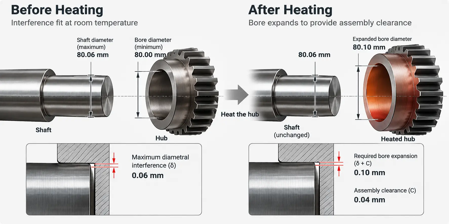
Interference, thermal expansion and assembly clearance in a shrink fit
2. How to Calculate Shrink Fit Heating Temperature
For a simple shaft-and-hub assembly, the required heating temperature can be estimated using thermal expansion.
The following calculation assumes that the outer component is heated approximately uniformly while the shaft remains near its initial temperature.
Step 1 — Calculate the Required Expansion
Required Bore Expansion = Maximum Interference + Assembly Clearance
Step 2 — Calculate the Temperature Rise
ΔT = (δ + C) / (α × D)
Where:
— ΔT = required temperature rise (°C)
— δ = maximum diametral interference (mm)
— C = required diametral assembly clearance (mm)
— α = average coefficient of linear thermal expansion (1/°C)
— D = fit diameter (mm)
The estimated component temperature is:
Heating Temperature = Initial Temperature + ΔT
Example: Heating a Steel Hub onto an 80 mm Shaft
Suppose a steel hub must be heated before being assembled onto a shaft.
| Parameter | Example Value |
|---|---|
| Fit Diameter | 80 mm |
| Maximum Interference | 0.06 mm |
| Required Assembly Clearance | 0.04 mm |
| Assumed Steel Expansion Coefficient | 12 × 10&supminus;&sup6; /°C |
| Initial Temperature | 20°C |
First, calculate the required bore expansion:
0.06 + 0.04 = 0.10 mm
Then calculate the temperature rise:
ΔT = 0.10 / (12 × 10&supminus;&sup6; × 80)
Required temperature rise ≈ 104°C
Add the initial temperature:
20 + 104 = 124°C
Under these assumptions, the hub needs to reach approximately 124°C to provide the calculated expansion.
The 0.04 mm assembly clearance is an illustrative assumption, not a standard allowance for every 80 mm fit. The actual clearance should be selected according to the assembly method and verified in practice.
The result is also an initial calculation rather than a final equipment setting. Actual heating conditions, temperature limits and heat loss during assembly still need to be considered.
If both components change temperature significantly, the expansion or contraction of both parts must be included in the calculation.
3. Why Might Parts Still Fail to Assemble at the Calculated Temperature?
A hub may reach the calculated temperature and still be difficult to fit onto the shaft.
This does not always mean the temperature needs to be increased.
Several problems can reduce the available clearance or prevent the components from being assembled correctly.
| What Happens During Assembly? | What Should Be Checked? |
|---|---|
| The shaft cannot enter the bore | Actual interference, bore expansion and temperature distribution |
| The shaft enters but becomes stuck | Assembly clearance, cooling during insertion and alignment |
| Some parts assemble successfully while others fail | Dimensional tolerances and heating consistency |
| The displayed temperature is correct but assembly is difficult | Temperature measurement location and actual bore expansion |
Uneven Heating
During rapid heating, the surface and inner regions of a component may not reach the same temperature.
For example, a temperature sensor may indicate that the heating target has been reached, while the bore has not expanded sufficiently.
The heating method and measurement location should match the actual workpiece geometry.
Heat Loss Before Assembly
A heated hub begins losing heat to its surroundings after heating stops.
If the component must be moved to another station, the bore may contract before the shaft is fully inserted.
For larger or heavier components, transfer time and positioning can become important parts of the assembly process.
Incorrect Dimensions or Poor Alignment
Even with sufficient heating, an oversized shaft, undersized bore or alignment problem can prevent smooth assembly.
If the parts become stuck, forcing them together may damage the mating surfaces.
Before increasing the heating temperature, check the actual dimensions, heating condition and assembly sequence.
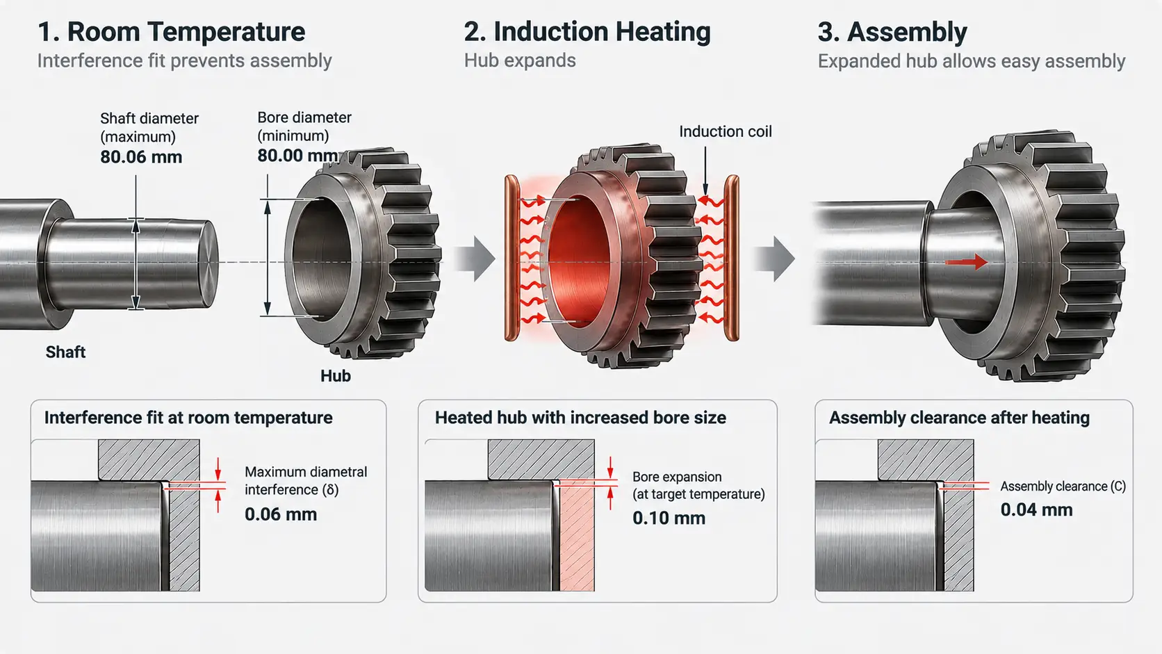
Calculated temperature vs. actual assembly
4. How to Choose a Practical Heating Temperature
The calculated temperature gives a useful starting point, but the production target should be established through actual assembly trials.
For example, the previous calculation gave a theoretical hub temperature of approximately 124°C.
That does not mean every suitable heating system should automatically be set to 124°C. The component may cool during transfer, and the measured surface temperature may not fully represent the bore expansion.
A practical heating process should answer three questions.
① Is the Temperature High Enough for Assembly?
The heated bore must provide enough clearance at the time the shaft is inserted.
Check the actual fit dimensions, temperature distribution and time between heating and assembly.
② Is the Temperature Safe for the Component?
The heating target must remain within the limits permitted by the material and component condition.
Heat-treated parts, coated surfaces and temperature-sensitive assemblies may have additional restrictions.
If the calculated temperature exceeds the permissible limit, review the interference, assembly clearance and assembly method instead of simply increasing the heat.
In some applications, cooling the shaft can reduce the amount of heating required for the outer component. However, the dimensional changes and handling requirements of both parts must be considered.
③ Can the Same Result Be Repeated in Production?
A process that works for one component may not work consistently across a batch if dimensions, heating conditions or assembly timing vary.
During process trials, check:
— Whether parts within the specified tolerance range can be assembled
— Whether heating is sufficiently consistent
— Whether the available assembly time is adequate
— Whether the finished assembly meets its dimensional and functional requirements
The production heating target should be based on these results, not only on a calculated temperature.
5. How Induction Heating Supports Shrink Fitting
Induction heating is used for shrink fitting gears, hubs, sleeves, motor components and other metal parts.
Instead of heating an entire assembly in a furnace, an induction coil can be designed to heat the required component or region.
This can be useful when the heating process must be coordinated with positioning, transfer and assembly.
Coil Design and Heating Distribution
The induction coil should match the component geometry and the region that needs to expand.
For example, a gear hub and a long sleeve may require different coil arrangements to obtain suitable heating conditions.
The goal is not simply to heat the surface quickly, but to achieve the expansion needed for assembly without exceeding the component’s temperature limits.
Temperature Monitoring and Process Control
Temperature monitoring can help maintain consistent heating conditions between parts.
However, sensor readings should be verified against the actual workpiece and assembly result, especially when heating is rapid or temperature distribution is uneven.
For more information about temperature feedback and power control, see Induction Heating Temperature Control: Power Control vs. Temperature Feedback.
Coordinating Heating and Assembly
In repeated production, heating time, transfer distance and positioning should be considered together.
An automated shrink fitting system may combine induction heating with controlled handling and assembly to reduce variation between cycles.
For equipment selection considerations, see Before You Buy an Induction Shrink Fitting Machine: 6 Decisions That Matter.
Key Takeaway
Shrink fit heating temperature can be estimated from the maximum interference, assembly clearance, fit diameter and material thermal expansion. The calculation provides a starting point; a reliable production temperature also depends on actual bore expansion, heat loss, component limits and assembly timing.
Frequently Asked Questions
Click a question to expand the answer.
How much assembly clearance should I add?
There is no standard allowance for every fit. The clearance is selected according to the assembly method and verified in practice; the 0.04 mm used in the example is illustrative, not a fixed rule.
Can cooling the shaft reduce the required heating temperature?
Yes. In some applications cooling the shaft reduces the amount of heating needed for the outer component, but the dimensional changes and handling requirements of both parts must be considered.
Why might the parts still not assemble at the calculated temperature?
The calculated value is only a starting point. Uneven heating, heat loss during transfer, incorrect dimensions or poor alignment can all reduce the available clearance, so check these before increasing the temperature.
Is the calculated temperature the final equipment setting?
No. It is an initial calculation. Actual heating conditions, temperature limits and heat loss during assembly still need to be considered, and the production target should be confirmed through assembly trials.
Discuss Your Shrink Fitting Application
Kechuang provides customized induction heating equipment and shrink fitting solutions for gears, hubs, sleeves and other industrial components. Share your workpiece dimensions, material, interference requirements and production conditions to discuss a suitable heating and assembly process.


