Gear Tooth Induction Hardening: Hardness Pattern and Case Depth
How Gear Geometry, Load Requirements and Process Selection Define the Hardened Zone
Gear tooth induction hardening is not simply a matter of making the tooth surface hard. The required result depends on where the hardened zone is needed, how deep it should extend, and how the gear will be loaded in service. Those requirements should be defined before the induction process is selected.
2. Where Should the Gear Tooth Be Hardened?
3. What Determines the Required Hardness Pattern?
4. How the Required Pattern Affects the Induction Hardening Method
5. Case Depth Is More Than a Single Number
6. How Is the Finished Hardness Pattern Verified?
7. Why the Actual Pattern May Differ From the Specification
8. What Should Be Specified Before Gear Induction Hardening?
1. What Does the Hardness Pattern Mean on an Induction-Hardened Gear?
The hardness pattern describes the location and shape of the hardened region around a gear tooth. Depending on the design, it may cover mainly the tooth flank, extend into the tooth root and root fillet, or follow a larger portion of the tooth contour.
This is different from a hardness profile. A hardness pattern answers the question of where the hardened region is located. A hardness profile describes how hardness changes across a section or with depth below the surface.
Two gears can therefore have similar surface hardness readings while having quite different hardened patterns beneath the surface.
2. Where Should the Gear Tooth Be Hardened?
The required hardened area should follow the way the tooth carries load rather than a fixed rule applied to every gear.
Tooth Flank. The flank is the working surface that comes into repeated contact with the mating gear or pinion. Tooth flank hardening is generally concerned with resistance to wear and contact fatigue. Pitting is one possible form of contact-fatigue damage in this region.
Tooth Root and Root Fillet. Bending stress is concentrated around the tooth root and the transition into the root fillet. For gears where root strength is a major design concern, the specified hardness pattern may extend farther into this area. That does not mean every gear requires the root to be hardened in the same way; the required coverage depends on the design and duty.
Tooth Tip. The tip may or may not be included in the required pattern. Its treatment depends on tooth geometry, the selected hardening method and the engineering specification.
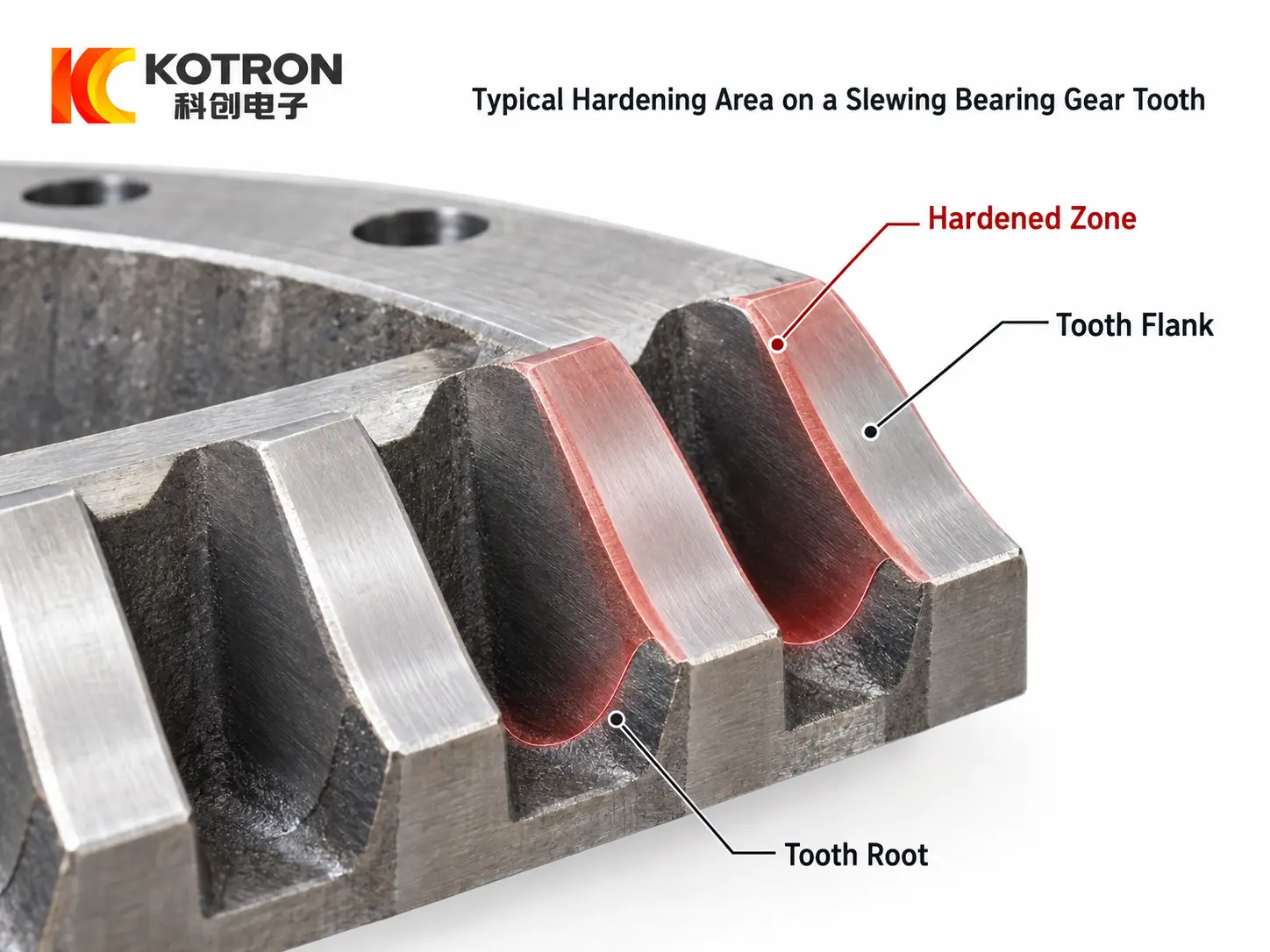
Tooth flank, root and root fillet hardening zones on a gear tooth.
The important point is that a gear tooth hardness pattern should be defined around the intended loading condition, not simply by trying to harden the largest possible area.
3. What Determines the Required Hardness Pattern?
Service load is the starting point. A gear subjected mainly to repeated contact loading may place more emphasis on the flank, while another application may require additional attention to the root and root fillet because of bending stress.
Tooth geometry also matters. Gear module, tooth size and the shape of the tooth space influence both the required hardened zone and how induction energy can be applied to it.
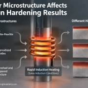
Material and prior microstructure must also be considered. Induction hardening changes the surface region of an already manufactured component, so the response of the steel to heating and quenching affects the resulting hardness and depth.
The specification then has to connect these factors with the required surface hardness and case depth, or effective hardened depth where that terminology is used.
There is no universal “best” gear hardening pattern. Deeper is not automatically better, and extending the hardened zone farther toward the root is not automatically an improvement. Excessive emphasis on hardness alone can ignore other requirements such as core toughness.
Gear durability also depends on conditions outside the heat-treatment process, including tooth geometry, meshing, lubrication, alignment and the condition of the mating gear or pinion.
4. How the Required Pattern Affects the Induction Hardening Method
The desired hardness pattern influences how the gear is heated.
With spin hardening, the gear is rotated while the required region is heated around its circumference. This approach can be suitable where the gear geometry and required pattern allow the tooth region to be treated in this manner.
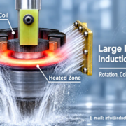
For larger gears or applications that require more localized control, tooth-by-tooth induction hardening may be used. Processing can be concentrated on individual tooth spaces or selected portions of the tooth geometry.
Gap-by-gap processing is one form of localized treatment in which the inductor works through successive tooth spaces.
Contour hardening refers to producing a hardened region that follows the tooth contour more closely. It should not be treated as the automatic choice for every gear; the required pattern and practical process capability still determine whether it is appropriate.
The method is therefore selected to reproduce the specified hardness pattern as reliably as possible, rather than selecting a process first and accepting whatever pattern it produces.
5. Case Depth Is More Than a Single Number
Surface hardness alone does not fully describe the condition of an induction-hardened gear tooth.
The hard layer must also extend to an appropriate depth. In shop-floor communication this is often referred to as case depth, while more specific gear specifications may use terms such as effective hardened depth.
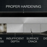
The measurement location matters. A depth measured on the flank does not automatically describe what has been achieved at the root fillet. If both areas are important to the design, the specification and inspection plan should make those locations clear.
This is one reason a drawing that states only a surface hardness value can leave too much room for interpretation. The required hardened region and the depth at relevant tooth locations should be defined together.
6. How Is the Finished Hardness Pattern Verified?
The finished gear cannot be fully evaluated by looking at its surface.
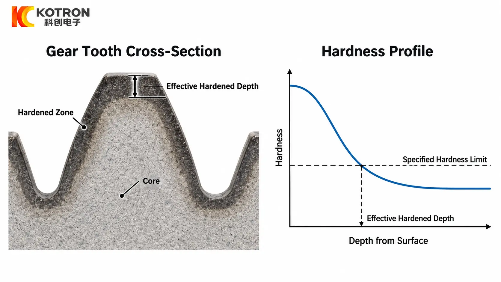
Hardness profile and effective hardened depth across a gear tooth cross-section.
A common verification approach is to examine a cross-section of the hardened tooth. The sample may be cut, prepared and polished so that the hardened region can be evaluated. Macroetching can help reveal the general shape of the transformed zone.
Hardness measurements across the section provide additional information. A hardness traverse or hardness profile can show how hardness changes from the surface toward the core and can be used to determine the effective hardened depth according to the applicable specification.
These methods answer different questions. A visible etched pattern shows the overall shape of the hardened region, while hardness measurements establish whether that region actually meets the required hardness criterion.
7. Why the Actual Pattern May Differ From the Specification
Even when the target pattern is clearly defined, the production result still depends on process control.
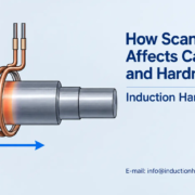
Inductor position and alignment affect coupling with the tooth. Frequency, power and heating time influence how energy is distributed and how deeply heat penetrates. In scanning or localized processes, movement conditions can change the result from one area of the tooth to another.
Quenching also matters. The position and coverage of the quench can affect the final transformation, while heat remaining in adjacent regions may contribute to back tempering under some process conditions.
For this reason, the target hardness pattern has to be confirmed on the actual process rather than assumed from machine settings alone.
8. What Should Be Specified Before Gear Induction Hardening?
A useful gear tooth induction hardening specification should provide more than a single hardness number.
The information normally starts with the gear drawing, material, gear module and tooth geometry. It should then identify the required hardened area, surface hardness, case depth or effective hardened depth, and whether the flank, root or root fillet requires specific coverage.
Production requirements also matter because they can affect the practical hardening method used to reproduce the specified pattern.
The key engineering question is therefore not simply, “How hard should the gear tooth be?” It is:
Where should it be hardened, how deep should that hardened region extend, and how will the result be verified?
For large internal or external slewing gears, the same principles also guide the configuration of a slewing bearing gear induction hardening machine. The equipment should follow the drawing and hardening specification, not replace them.
Key Takeaway
Gear tooth induction hardening is defined by three questions — where the hardened region is located, how deep it should extend, and how the result will be verified. Surface hardness alone is not enough, and the pattern must follow the actual loading condition rather than a fixed rule applied to every gear.
Frequently Asked Questions
Click a question to expand the answer.
What is the difference between a hardness pattern and a hardness profile?
A hardness pattern describes where the hardened region is located around a tooth, while a hardness profile describes how hardness changes across a section or with depth below the surface. Two gears can have similar surface hardness yet different hardened patterns beneath the surface.
Does every gear need the tooth root hardened?
Not necessarily. Bending stress concentrates around the root and root fillet, so root hardening matters where root strength is a design concern. The required coverage depends on the design and duty rather than a fixed rule applied to every gear.
Is a deeper case always better?
No. Deeper is not automatically better, and extending the hardened zone farther toward the root is not automatically an improvement. Excessive emphasis on hardness alone can ignore other requirements such as core toughness.
How is the finished hardness pattern verified?
A cross-section is cut, prepared and polished, then macroetched to reveal the transformed zone. A hardness traverse shows how hardness changes from the surface toward the core and determines the effective hardened depth.
Why might the actual pattern differ from the specification?
Inductor position, frequency, power, heating time, movement and quench coverage all affect the result. The target hardness pattern must be confirmed on the actual process rather than assumed from machine settings alone.
Specify the Hardened Zone Before Selecting the Method
Send your gear drawing, material and heat-treatment requirement. We will evaluate the required hardness pattern, case depth and verification approach together, then recommend an induction hardening configuration for your gear.