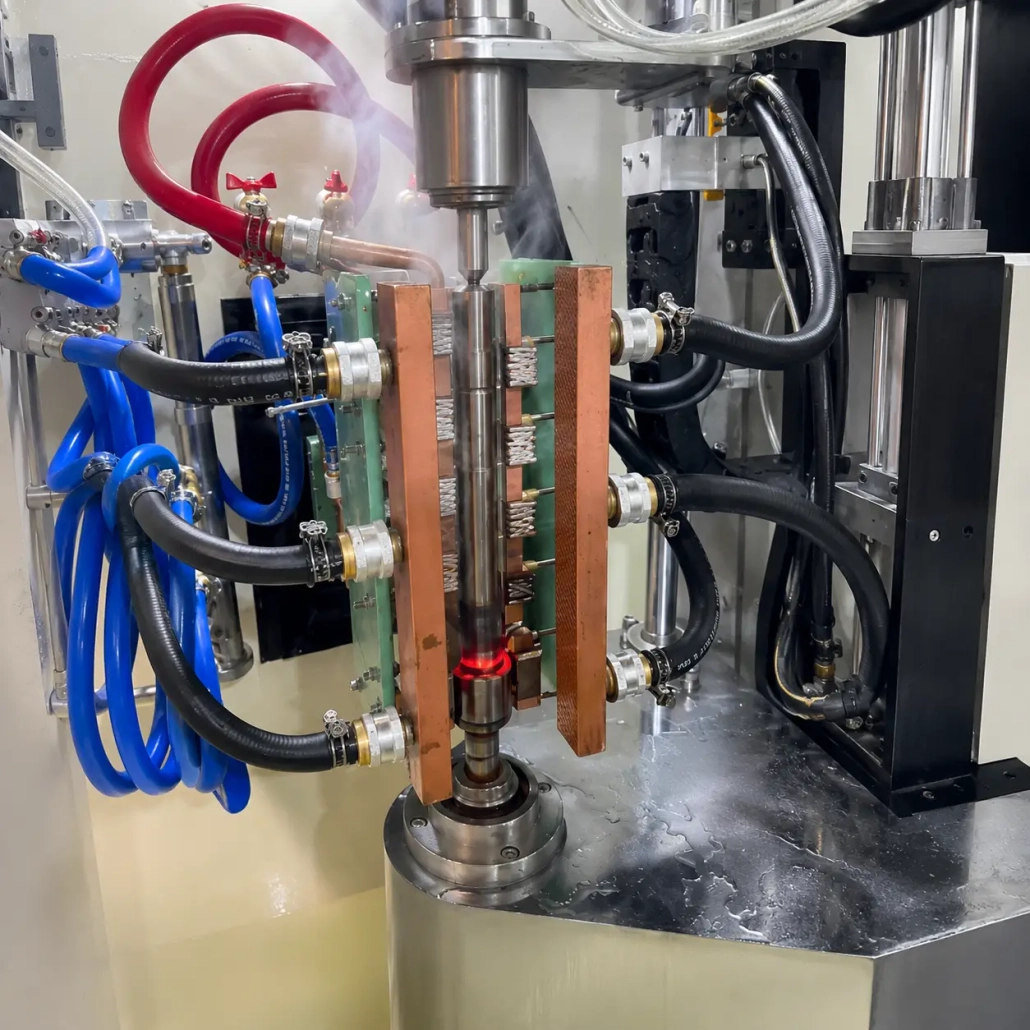
Spline Shaft Induction Hardening Machine
Ⅰ. See the Spline Shaft Hardening Process
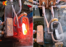
The video shows a spline shaft being hardened by a one-shot induction process.
After the workpiece is positioned, the complete target spline section is heated at the same time. The inductor does not scan up or down the shaft during heating. Once the required heating condition is reached, the full heated section is spray quenched immediately.
The process can be summarized as:
1. Positioning
2. One-Shot Induction Heating
3. Overall Spray Quenching
4. Unloading
This is different from conventional scanning hardening, where a shorter heating zone travels progressively along the workpiece.
For suitable spline lengths and geometries, one-shot hardening provides a direct way to heat and quench the complete splined area within one cycle.
Ⅱ. How One-Shot Spline Shaft Induction Hardening Works
A splined section is more complex to heat than a plain cylindrical surface.
The spline profile contains tooth tips, flanks, roots and grooves. These features create different electromagnetic coupling conditions around the profile, so the heating result cannot be controlled by power alone.
In a one-shot process, the inductor is designed to cover the complete target spline length. The workpiece remains at the hardening position while induction power is applied for a programmed period.
When heating is complete, the quenching system cools the entire heated section rather than following a moving heating zone.
Several variables work together:
• Induction power
• Operating frequency
• Heating time
• Inductor geometry
• Coupling between the inductor and workpiece
• Spline dimensions
• Material
• Quenching timing and spray arrangement
The aim is to establish the required hardened pattern on the spline section, not simply to raise the surface to the highest possible temperature.
Surface hardness and effective case depth therefore need to be specified according to the actual shaft material, spline geometry and drawing requirements. They should not be treated as fixed values for every spline shaft.
Ⅲ. Dedicated Inductor Design for the Spline Profile
The inductor is one of the most important parts of a spline shaft hardening system.
A plain shaft can often be heated with a relatively simple circular inductor. A splined section requires more careful field distribution because the surface profile changes continuously between the tooth tip and root.
The inductor is therefore developed around the actual workpiece drawing.
Important design information includes:
• Spline outside diameter
• Root diameter
• Tooth profile
• Spline length
• Hardened area
• Required case depth
• Available space around the workpiece
• Required heating cycle
Magnetic flux concentrators may also be used where required to influence the electromagnetic field and concentrate energy around selected areas of the spline.
The supplied technical information for the company’s induction hardening platforms also emphasizes controlled inductor-to-workpiece spacing, structural rigidity and insulation in customized inductor design.
For this reason, selecting an inductor only from the outside diameter of the shaft is rarely sufficient. Two spline shafts with similar diameters can still require different coil structures because their tooth geometry and hardened lengths are different.
Ⅳ. Machine and Hardening Process Control
The machine has to position the spline section consistently relative to both the inductor and the quenching system.
A vertical machine arrangement is suitable for many shaft-type components. The workpiece can be clamped and positioned so that the required spline section enters the fixed heating station before the hardening cycle begins.
Depending on the project configuration, the machine control can coordinate:
• Workpiece positioning
• Clamping
• Heating time
• Induction power
• Heating sequence
• Quenching delay
• Spray quenching time
• Cycle completion
• Loading and unloading signals
The company’s existing vertical CNC hardening platforms support manual and automatic operation and can be configured for fixed-position, segmented and scanning hardening of shaft-type components.
For the spline shaft process shown on this page, however, axial scanning is not used during heating. The complete target spline area is heated at one position.
This distinction matters when evaluating the machine. Travel speed and scanning length, for example, are important parameters for a scanning process but are not the main process variables for this one-shot application.
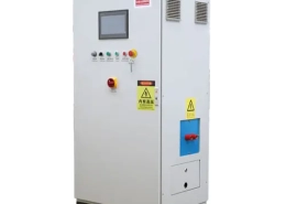
Ⅴ. IGBT Induction Power with DSP Digital Control
The induction power supply controls how electrical energy is delivered during each heating cycle.
Available systems use IGBT power conversion with DSP digital control. The supplied equipment information lists digital power regulation and control modes including constant-current and constant-power operation, with temperature-related control available in corresponding configurations.
For spline shaft hardening, induction power and operating frequency should be selected from the complete process requirement rather than shaft diameter alone.
Relevant factors include:
Material + Spline Geometry + Heated Length + Required Case Depth + Heating Time + Production Rate
A short spline with a relatively small heated mass can require a very different configuration from a long splined section, even when both shafts have a similar outside diameter.
This is why we do not divide spline shafts into fixed “small,” “medium” and “large” power categories.
The power supply, inductor and hardening cycle should be evaluated together.
Ⅵ. Single-Station and Multi-Station Configurations
The hardening station can be arranged around the required production volume and workpiece handling method.
A single-station configuration provides one hardening position. Loading and unloading can be manual or automated depending on the project.
For higher production requirements, a multi-station indexing machine can be used so that different operations are arranged across several stations according to the production cycle.
The supplied equipment information includes double-station and four-station indexing hardening platforms. Workpiece rotation, indexing mechanisms and automatic loading arrangements are available on corresponding systems.
For automatic production, a gantry loading system can also be configured. The existing company platform uses servo-driven horizontal and vertical movement with grippers to transfer shaft-type parts between the loading position and the hardening station.
Possible configurations include:
• Single-station machine
• Multi-station indexing machine
• Manual loading
• Gantry automatic loading
• Automatic unloading
• Conveyor connection
• Recipe management
• Production-line communication
The final arrangement depends on part weight, shaft dimensions, cycle time and factory layout.
Ⅶ. Optional Process Monitoring
For repeated production, the hardening system can be equipped with process monitoring and recording functions.
The available monitoring platform can collect data such as induction current, voltage, frequency and energy. With the corresponding sensors, quenching-medium flow, cooling-water flow and temperature can also be monitored.
Typical functions include:
• Real-time process monitoring
• Heating curve recording
• Upper and lower limit alarms
• Workpiece recipe storage
• Historical production records
• Process data traceability
Monitoring does not replace hardness testing or case-depth inspection of the finished shaft. Its purpose is to record whether the production cycle remained within the established process window and to make abnormal cycles easier to identify.
This is particularly useful when the same spline shaft is produced repeatedly in batch production.
Ⅷ. Frequently Asked Questions
Click a question to expand the answer.
Is this a scanning induction hardening process?
No. The process shown in the video is one-shot induction hardening. The complete target spline section is heated at one position and then spray quenched. There is no axial scanning during the heating cycle.
Does one-shot hardening work for every spline shaft?
Not necessarily. Spline length, tooth geometry, workpiece material, required hardened pattern and production conditions all affect the choice of process. Long splined sections or different hardening requirements may be better suited to segmented or scanning methods. The process should be selected after reviewing the workpiece drawing.
What hardness and case depth can the machine achieve?
There is no single hardness or case-depth value that applies to every spline shaft. The result depends on the material, original heat-treatment condition, spline geometry and required hardening specification. Please provide the required surface hardness and effective case depth from your drawing or technical standard so the heating process can be developed around those requirements.
Can one machine process different spline shafts?
Yes, provided the parts remain within the mechanical and electrical capacity of the machine. Different spline shafts may require separate inductors, fixtures and process recipes. If several workpieces need to be processed on the same machine, it is better to review all of their drawings during the equipment selection stage.
What information is needed for machine selection?
Please send: spline shaft drawing, material and grade, overall dimensions, spline dimensions, area to be hardened, required surface hardness, required effective case depth, production quantity or required cycle, and manual or automatic loading requirement.
A drawing with the required hardened area clearly marked is especially useful for determining the inductor, induction power, hardening method and machine configuration.
Ⅸ. Send Us Your Spline Shaft Drawing
A spline shaft induction hardening system should be developed around the actual part rather than selected from a machine model alone.
Send us your workpiece drawing, material, hardened area, hardness requirement, case depth and production requirement. We can evaluate the one-shot hardening process, inductor arrangement, induction power, quenching method, machine structure and automation configuration together.
Send Your Workpiece Drawing →
Request a Technical Proposal →