
Tại sao nhiệt kế hồng ngoại cho kết quả đo nhiệt độ không chính xác trong hệ thống sưởi cảm ứng
Độ phát xạ như thế nào, Reflections and Measurement Conditions Affect Pyrometer Accuracy
Infrared pyrometers are commonly used to monitor workpiece surface temperature during induction heating. They provide fast, non-contact measurements, but the displayed temperature may not always represent the actual temperature of the intended surface.
An unexpected reading can result from changes in metal emissivity, reflected radiation, incorrect spot positioning or interference along the optical path. These problems are particularly relevant when heating is localized, workpieces are moving or surface conditions change during the heating cycle.
Before adjusting the induction heating process, engineers need to establish whether the temperature has actually changed or the measurement has become unreliable.
2. How Reflections and Optical Conditions Cause Measurement Errors
3. Why Readings Fluctuate During Induction Heating
4. How to Check Whether the Pyrometer Reading Is Reliable
1. Why Infrared Pyrometers Can Misread Metal Temperatures
An infrared pyrometer estimates temperature from the thermal radiation received from a target. The calculation depends on the radiation emitted by the surface and the assumptions used by the instrument.
Two metal surfaces at the same temperature can produce different infrared signals. This is one reason infrared temperature measurement of steel and other metals requires careful attention to tình trạng bề mặt.
Emissivity and metal surface condition
Emissivity describes how effectively a surface emits thermal radiation compared with an ideal blackbody at the same temperature.
For a conventional single-wavelength pyrometer, an incorrect emissivity setting can produce a substantial temperature error. The actual emissivity depends on the material, hoàn thiện bề mặt, oxy hóa, nhiệt độ, viewing direction and measurement wavelength.
Consider a polished steel surface and an oxidized surface of the same steel. Even at the same temperature, they may emit different amounts of infrared radiation within the instrument’s measurement band.
Using an identical emissivity setting for both surfaces can therefore produce different indicated temperatures.
The direction of the error matters. For a hot target surrounded by a cooler environment, setting the emissivity higher than its actual value generally produces a reading that is too low in single-wavelength measurement. Reflected radiation and other conditions can complicate this relationship.
Material emissivity tables are useful references, but their values should not be treated as universally applicable settings.
Keller Pyrometer Systems explains the relationship between emissivity, surface condition and measurement accuracy.
Why oxidation can change the reading during heating
A steel surface may oxidize as its temperature rises. The developing oxide layer can change its spectral emissivity, so a pyrometer setting established before heating may become less representative later in the cycle.
Ví dụ, a change in the displayed temperature may partly reflect a change in surface radiation characteristics rather than an equivalent change in actual temperature.
The effect is not always in the same direction. It depends on the material, oxide layer, wavelength and surrounding radiation.
This becomes relevant when comparing temperature records from workpieces with different surface finishes, oxide conditions or preparation methods.
A repeatable pyrometer setting does not necessarily provide comparable measurements if the measured surfaces are different.
Does measurement wavelength make a difference?
Có. Because metal emissivity varies with wavelength, two pyrometers operating in different spectral bands may respond differently to the same surface.
Shorter-wavelength pyrometers can reduce sensitivity to certain emissivity errors when measuring sufficiently hot metals, although the appropriate wavelength depends on the temperature range and application.
Two-color, or ratio, pyrometers can compensate for some changes in emissivity or optical transmission when their underlying measurement assumptions remain valid. They are not immune to errors caused by changing spectral characteristics, unsuitable targets or unfavorable optical conditions.
Neither instrument type eliminates the need to verify the measurement arrangement.
2. How Reflections and Optical Conditions Cause Measurement Errors
Even with a suitable emissivity setting, the pyrometer may receive radiation that does not originate entirely from the intended measurement area.
Three practical concerns are reflected radiation, measurement spot size and the condition of the optical path.
Reflections from surrounding hot surfaces
Metal surfaces reflect some radiation from their surroundings. On a relatively low-emissivity surface, this reflected component can represent a significant portion of the signal reaching the pyrometer.
If radiation from a hotter nearby surface is reflected toward the sensor, the displayed temperature may be higher than the actual target temperature.
Changing the viewing angle can help investigate a suspected reflection, but it also changes the measurement geometry and may affect the observed emissivity. A changed reading after repositioning the sensor does not, tự nó, confirm that reflection was the cause.
The surrounding thermal environment should be considered when selecting a measurement position, particularly where exposed hot components are within the target’s reflective surroundings.
Measurement spot size and target alignment
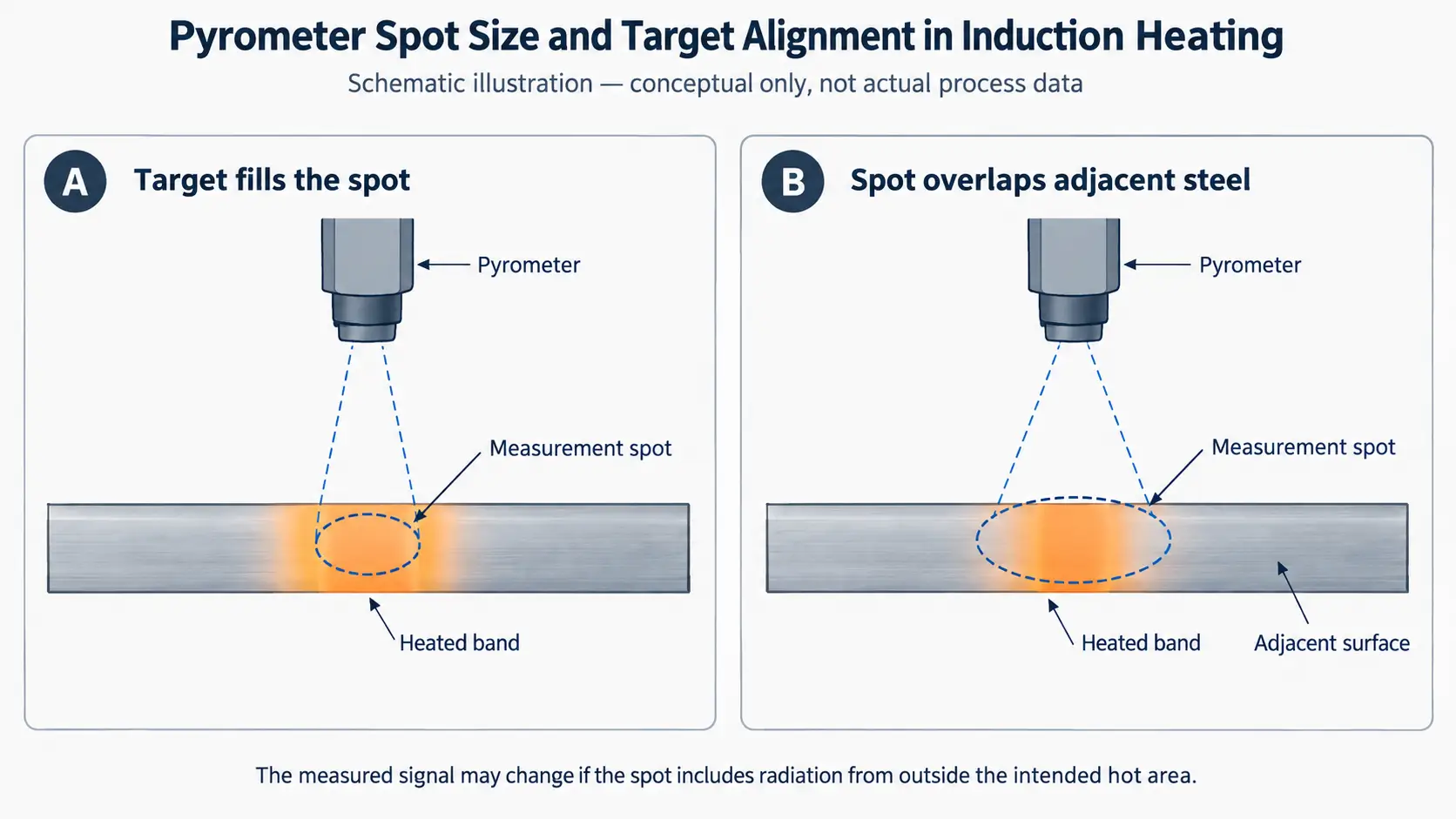
A pyrometer measures radiation from a finite area, not an infinitely small point.
The measurement spot depends on the instrument’s optics, focus and distance from the target. If the intended hot region does not adequately fill that spot, radiation from adjacent material can influence the reading.
This is a common concern in localized induction heating.
A narrow heated band may be surrounded by much cooler steel. If the measurement spot extends beyond the hot band, the displayed temperature may not represent the temperature of the intended region.
The same problem can occur when a moving workpiece shifts relative to a fixed sensor.
A laser aiming indicator, where fitted, does not necessarily show the entire measurement spot. The optical specifications should be checked at the actual installation distance, with sufficient allowance for target movement and positioning variation.
For small targets or sharp temperature boundaries, radiation received from outside the nominal spot may also influence the result through the instrument’s size-of-source effect.
Optical windows, smoke and contamination
Radiation must pass through the optical path before reaching the detector.
Bụi, khói, steam and other process emissions may affect the received signal through absorption or scattering. The extent of the error depends on the material present and the wavelength used.
Protective windows introduce another consideration. A window that is unsuitable for the pyrometer’s spectral range, or one covered with deposits, may reduce or otherwise alter the transmitted radiation.
A sensor can therefore be functioning normally while its displayed temperature becomes unreliable because the optical path has changed.
Keller’s discussion of pyrometer measurement errors identifies transmission losses and background radiation among the important influences on infrared temperature measurement.
3. Why Readings Fluctuate During Induction Heating
A fluctuating temperature signal is not necessarily evidence of unstable heating power.
Trong quá trình gia nhiệt cảm ứng, the observed surface may move, its condition may change and the temperature within the measurement area may be nonuniform. These effects can produce fluctuations even when the electrical output is stable.
Rapid heating and instrument response
Induction heating can produce rapid changes in local surface temperature.
If the pyrometer’s response time or signal averaging is too slow for the process, the displayed value may lag behind the actual temperature or smooth out short-duration peaks.
Increasing the response speed may reveal faster changes, but it can also make signal variations more apparent. Smoothing a signal does not establish that the measurement is accurate.
The response settings should reflect the temperature changes that need to be monitored.
Moving and rotating workpieces
Trong scanning induction heating, a fixed pyrometer may observe different surface regions as the workpiece travels through the measurement field.
If the spot crosses a temperature gradient, the indicated temperature can change even when the heating conditions remain unchanged.
Rotating components can present a similar problem. Periodic variations may result from actual circumferential temperature differences, changes in surface emissivity or movement of the observed area.
The first useful question is whether the fluctuations correspond to workpiece position or rotation.
A signal that repeatedly changes at the same location deserves a different investigation from one that changes unpredictably.
What about electromagnetic interference?
Induction heating equipment generates alternating electromagnetic fields. Under some installation conditions, interference can affect susceptible sensor electronics, signal cables or communication systems.
Tuy nhiên, electromagnetic interference should not be the default explanation for unstable readings.
Optical alignment, surface condition and genuine temperature variation should also be examined.
If interference is suspected, compare the timing of the disturbance with induction power operation and check the electrical installation according to the instrument manufacturer’s instructions.
Fluke Process Instruments discusses electromagnetic interference alongside emissivity, reflections and optical problems as possible causes of incorrect infrared temperature indications.
4. How to Check Whether the Pyrometer Reading Is Reliable
When a pyrometer reports an unexpected temperature, verify the measurement conditions before changing heating power or process settings. The aim is to separate genuine workpiece temperature changes from measurement errors.
Start with the target and optical path
Confirm that the pyrometer observes the intended surface and that the target adequately fills the measurement spot at the installed distance.
For moving or rotating workpieces, check whether the observed area changes during operation. Inspect the lens and protective window for contamination, and look for possible reflections, khói, steam or intermittent obstructions.
Review emissivity and instrument settings
Check the actual surface condition, including oxidation and finish, against the configured emissivity and measurement wavelength.
Do not adjust emissivity simply to make the display match an expected temperature. Any adjustment should be supported by an appropriate reference or validated measurement method.
Also review the measurement range, response time and averaging settings, particularly when heating is rapid.
Separate sensor readings from signal transmission
If the controller shows a different temperature from the pyrometer display, examine signal scaling, wiring and communication settings.
For fluctuating readings, compare the disturbance with workpiece movement, surface changes and induction power operation. Investigate electrical interference where the evidence suggests it may be involved.
Verify uncertain measurements
If the reading remains questionable, compare it with a suitable independent reference under representative conditions.
The reference method must account for the material, measurement location, temperature range and response time. A contact sensor is not automatically more accurate on a rapidly heated surface, and agreement between two pyrometers does not prove either is correct.
Instrument calibration confirms performance under specified reference conditions. It does not establish that the installed sensor is accurately measuring the intended workpiece surface.
A reliable surface reading also has limits: it does not directly establish internal temperature or uniform heating throughout the component.
Where pyrometer measurements are used for closed-loop control, an inaccurate signal may influence the controller’s response. The distinction between measuring temperature and controlling induction power is covered in Kiểm soát nhiệt độ sưởi ấm cảm ứng: Kiểm soát quyền lực vs. Phản hồi nhiệt độ.
Chìa khóa mang đi: Before treating an unexpected pyrometer reading as a heating problem, confirm what surface the instrument is measuring, how radiation reaches the sensor and whether its settings match the actual measurement conditions.
Câu hỏi thường gặp
Bấm vào một câu hỏi để mở rộng câu trả lời.
Why does my pyrometer show a different temperature than the actual workpiece surface?
The reading depends on emissivity, reflected radiation, measurement spot size and the optical path. A change in any of these conditions can shift the displayed temperature without a corresponding change in the actual surface temperature. Verify these conditions before changing the heating process.
Do I need to change the emissivity setting when the steel oxidizes during heating?
Oxidation changes the surface’s spectral emissivity, so a setting established before heating may become less accurate later in the cycle. Re-check the setting against the actual oxidized surface, ideally with a suitable reference, rather than adjusting it only to match an expected temperature.
Is a two-color (ratio) pyrometer always more accurate?
Không nhất thiết. A two-color pyrometer can compensate for some emissivity and optical-transmission changes when its assumptions hold, but it is not immune to errors from changing spectral characteristics, unsuitable targets or unfavorable optical conditions. The measurement arrangement still needs to be verified.
Why does the reading fluctuate even when the induction power is stable?
The observed surface may move, rotate or have a nonuniform temperature, and the surface condition may change during heating. These effects can produce fluctuations even with stable electrical output. Check whether the variations correspond to workpiece position or rotation, and review the response-time and averaging settings.
Need help verifying your pyrometer measurements?
Contact KOTRON to discuss temperature measurement and control for your induction heating process.


