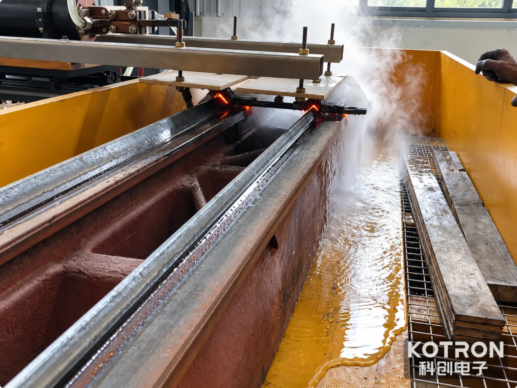
Machine Tool Bed Induction Hardening for Guideway Surfaces
Scanning Induction Heating and Spray Quenching for Long Machine Tool Guideways
Machine tool bed induction hardening is used to treat designated guideway surfaces on suitable machine beds. This application features a scanning induction hardening system for long guideway surfaces, combining localized induction heating with spray quenching along the treatment path.
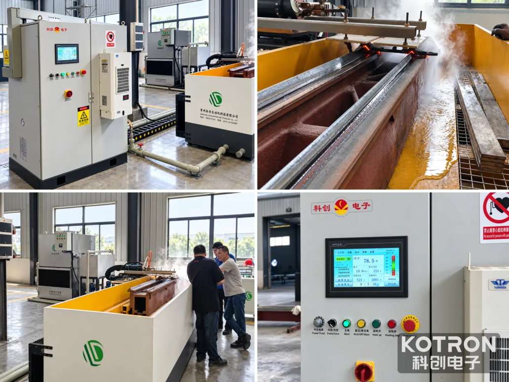
The installation shown in this case demonstrates the processing of a large machine tool bed using dedicated induction heating equipment. The heating arrangement, relative movement, and quenching process are coordinated to suit the guideway surface being treated.
The system is available as an industrial equipment solution. Its detailed configuration depends on the workpiece dimensions, guideway geometry, heat treatment requirements, and production conditions.
Ⅰ. Machine Tool Bed Guideway Hardening in Operation
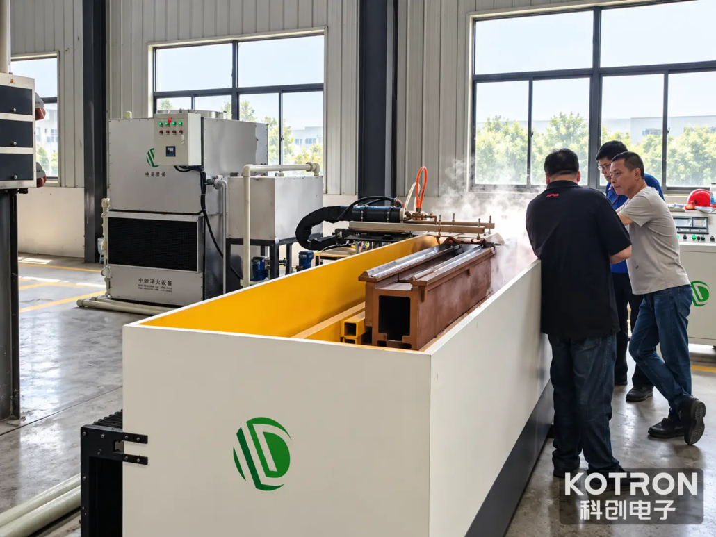
The video shows a large machine tool bed undergoing scanning induction hardening. The processing area includes the workpiece, induction heating equipment, a spray quenching arrangement, and an electrical control cabinet.
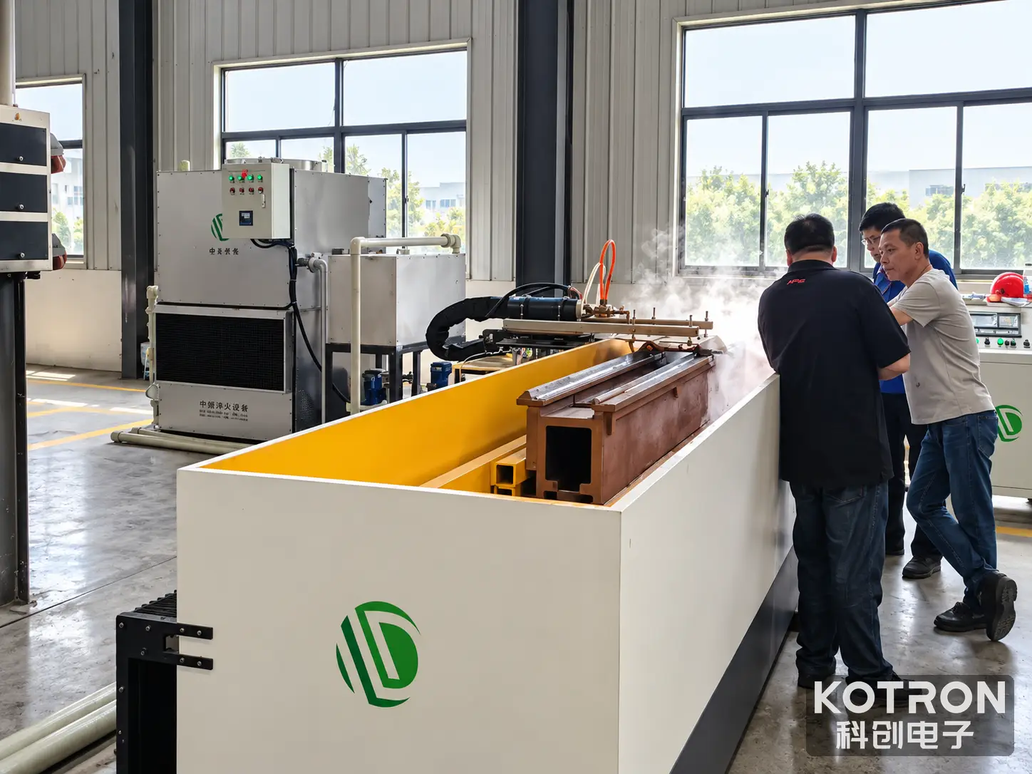
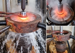
During the demonstrated operation, liquid is applied around the treatment zone, producing visible vapor and runoff. The footage provides a direct view of the industrial setup and the relationship between the guideway surface and the heating and quenching equipment.
The recorded process illustrates the application of scanning induction hardening to a long machine tool guideway. Specific operating parameters and final heat treatment results must be established from the equipment specification and workpiece inspection data.
Ⅱ. Workpiece and Treatment Area
The workpiece shown is a large machine tool bed with long guideway surfaces. These surfaces provide guiding and supporting functions for moving machine components and may require surface hardening to meet specified wear resistance and service requirements.
The treatment area and workpiece geometry are important when selecting a guideway induction hardening system.
Guideway geometry
The width, profile, and position of the surfaces to be treated influence inductor design and access to the workpiece.
Treatment length
The required hardening length determines the working travel needed for the scanning process.
Material
The steel grade and its initial condition affect hardenability and the achievable heat treatment results.
Dimensional requirements
Guideway alignment and dimensional tolerances must be considered when developing the heating and quenching process.
The exact material grade, guideway dimensions, target hardness, and effective hardened depth for this demonstration have not been confirmed. These values should be established from the actual workpiece specifications rather than inferred from photographs.
Ⅲ. Scanning Induction Heating and Spray Quenching
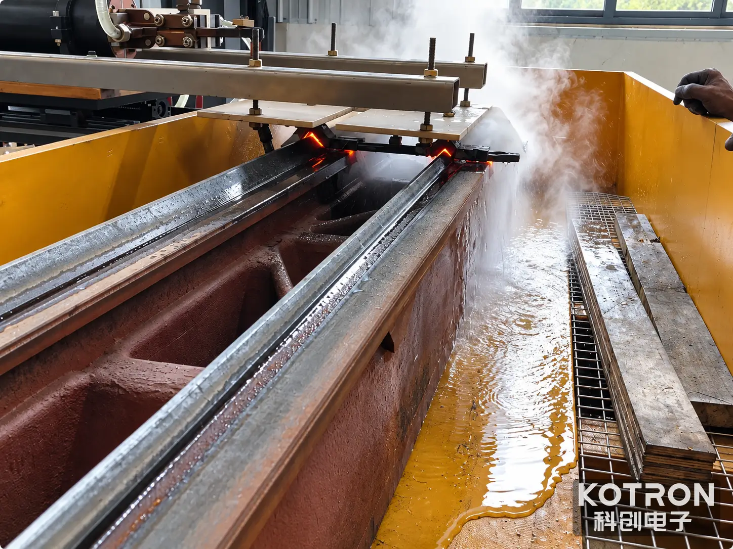
Scanning induction hardening progressively treats a designated surface through relative movement between the induction heating zone and the workpiece.
The inductor generates an alternating magnetic field, inducing electrical currents in the conductive workpiece and producing localized heat. For a suitable hardenable steel, the surface is heated under conditions established for the required hardening result.
As the treatment progresses along the guideway, the heating and quenching positions must be coordinated to achieve the intended thermal cycle.
The principal process considerations include:
Inductor geometry and coupling
These influence the distribution of heating across the guideway profile.
Heating power and frequency
These are selected according to the material, geometry, and required hardened depth.
Scanning speed
Relative movement affects the time the surface is exposed to the heating zone.
Quenching conditions
The cooling arrangement must suit the material and required transformation.
Process validation
Hardness, hardened depth, and dimensional requirements should be checked against the agreed acceptance criteria.
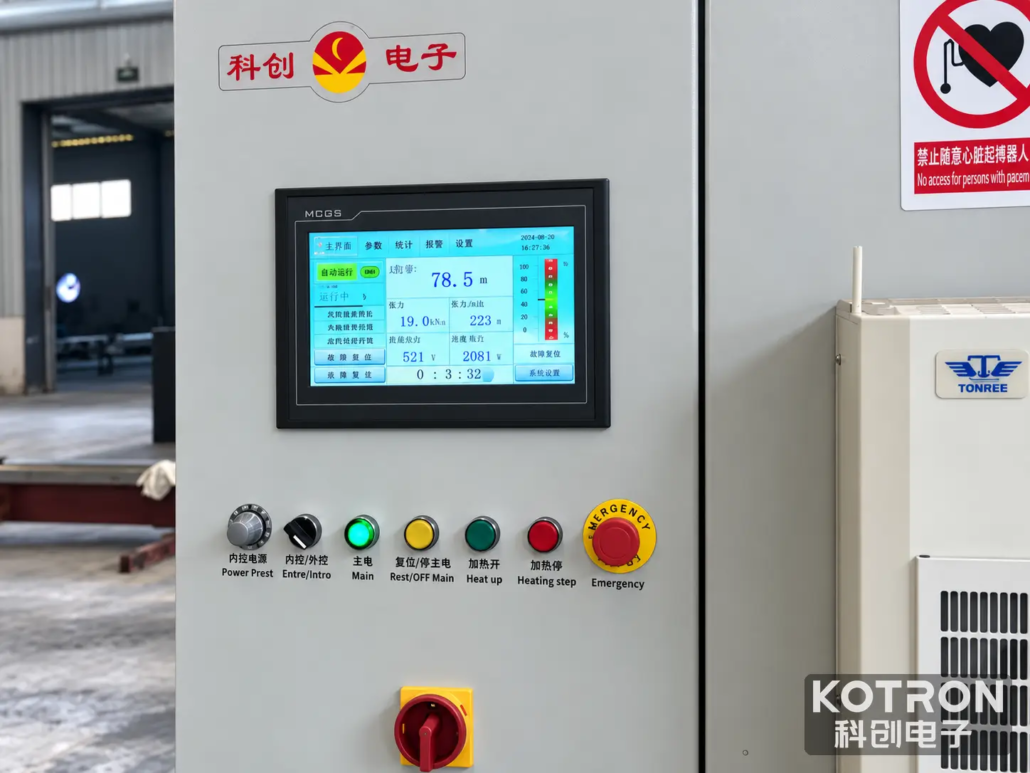
The appropriate combination of these variables must be determined for the actual workpiece. A control-screen reading alone cannot establish the final metallurgical properties of the treated surface.
Ⅳ. Equipment Arrangement and System Configuration
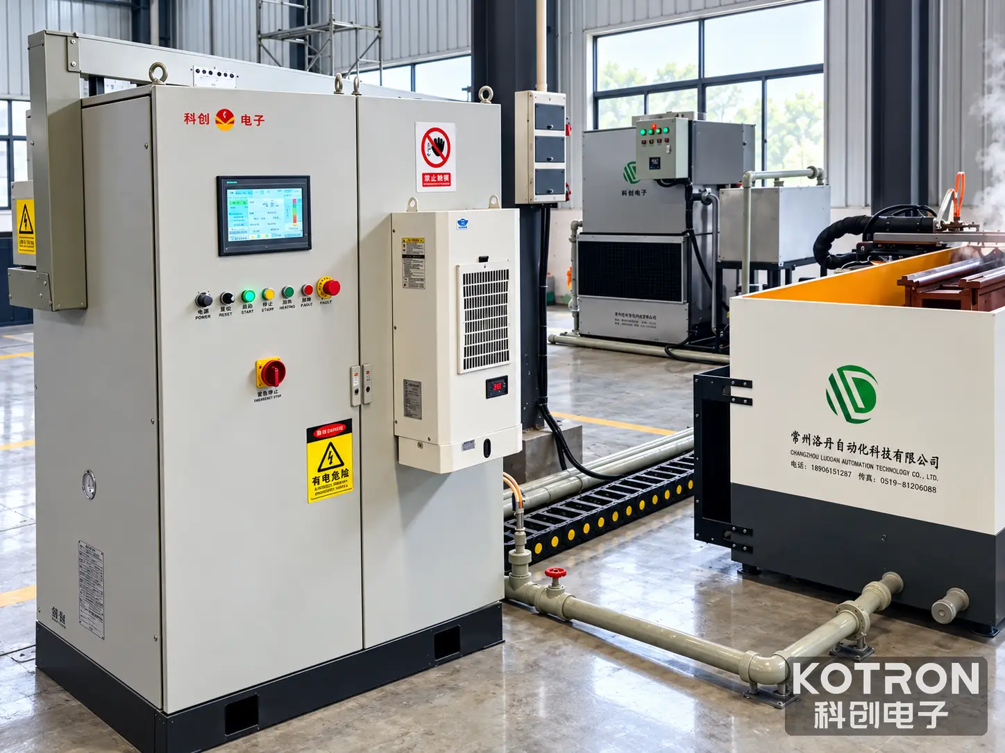
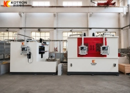
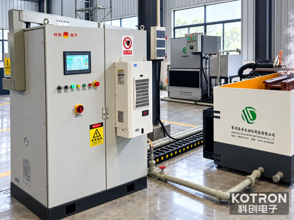
The installation shown includes a large workpiece positioned in a dedicated processing area, induction heating equipment, a quenching arrangement, and an electrical control cabinet.
The system is intended for the scanning treatment of machine tool bed guideways. Its detailed mechanical and electrical configuration should be specified according to the application rather than assumed from the appearance of a single installation.
Key configuration areas include:
Induction heating system
The power supply and inductor must be matched to the material, guideway profile, required treatment depth, and intended processing conditions.
Inductor and workholding
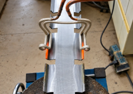
The inductor geometry and workpiece positioning arrangement must provide suitable access to the designated surface. Application-specific inductors or fixtures may be required for different guideway profiles.
Scanning mechanism
The motion arrangement must provide the relative movement needed to follow the specified treatment path. The mechanical implementation and working travel should be confirmed against the equipment specification.
Quenching arrangement
The quenching system must deliver the required cooling medium in coordination with the heating process. The delivery arrangement and process conditions require application-specific assessment.
Electrical controls
The control cabinet and operator interface form part of the illustrated installation. The available monitoring functions, operating sequence, motion controls, and automation scope must be confirmed for the actual system being supplied.
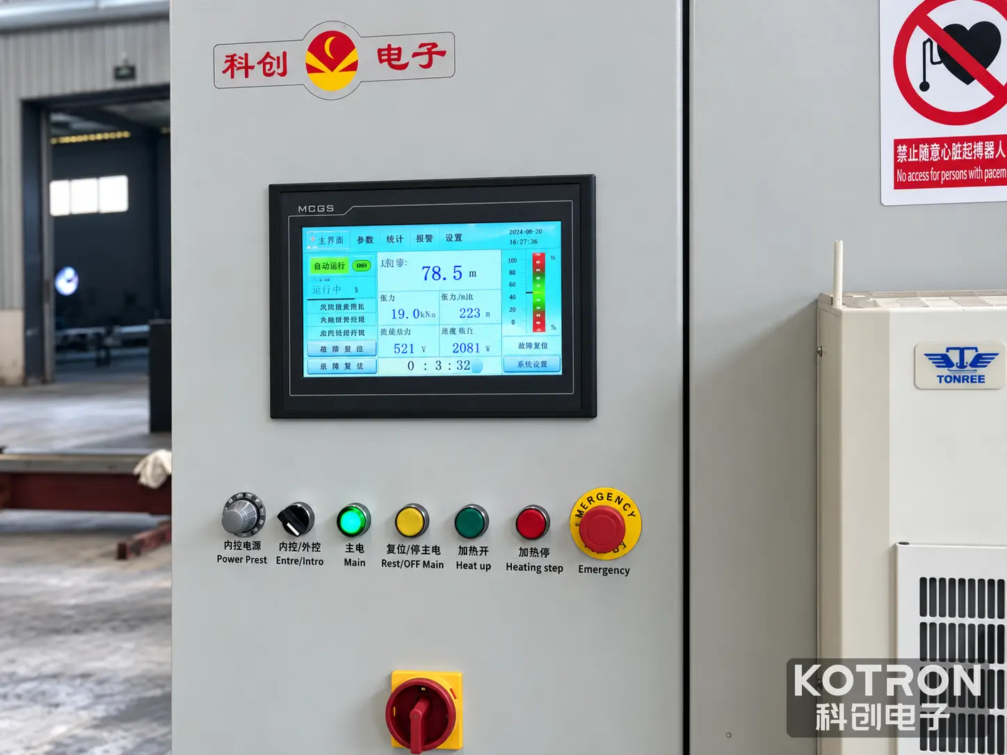
The photographs do not establish that every possible fixture, control function, or automation option is included in the standard supply. The final quotation should clearly identify the included equipment and any application-specific or optional components.
Ⅴ. Equipment Selection for Machine Tool Guideways
The equipment configuration should be determined from the workpiece and the required heat treatment results.
For an initial assessment, the most useful information is:
| Selection Input | Why It Matters |
|---|---|
| Workpiece drawing or photographs | Identify the guideway geometry and treatment area |
| Material grade, if known | Assess material suitability and hardenability |
| Main workpiece dimensions | Establish the equipment working envelope |
| Required hardening area and length | Determine the treatment path and working travel |
| Production requirements | Define the intended operating sequence and equipment scope |
If already available, the target surface hardness, effective hardened depth, dimensional tolerances, and inspection requirements should also be provided.
These details help determine the appropriate heating arrangement, inductor, motion system, and quenching configuration. Where the heat treatment requirements have not yet been established, the workpiece and intended application should be reviewed before finalizing the process.
Ⅵ. Frequently Asked Questions
What workpieces is this system intended for?
The demonstrated application involves long guideway surfaces on a large machine tool bed. Suitability for other workpieces depends on their geometry, material, treatment requirements, and the designed working range.
How does scanning induction hardening work?
The heating zone progresses along the designated guideway surface through relative movement between the inductor and workpiece. Spray quenching is coordinated with the heating process to achieve the required heat treatment conditions.
Can the system achieve a specified surface hardness and hardened depth?
These results depend on the workpiece material, initial condition, inductor design, heating parameters, scanning conditions, and quenching process. Required values should be agreed and verified through appropriate testing; they cannot be inferred from the equipment photographs alone.
Can the equipment configuration be customized?
The system configuration can be evaluated against the actual workpiece drawing and production requirements. The necessary inductor, fixtures, motion arrangement, quenching equipment, and control functions should be confirmed during technical assessment.
Ⅶ. Request a Machine Tool Guideway Induction Hardening Solution
For manufacturers processing long machine tool bed guideways, the appropriate induction hardening system depends on the workpiece geometry, specified treatment area, material, and production requirements.
KOTRON can review these application details to assess a suitable scanning induction hardening equipment configuration.
To begin an inquiry, please send your workpiece drawing or photographs, material information if available, main dimensions, required hardening area, and production requirements.
Manufacturers hardening square or rectangular guide rails may also review our four-side induction hardening machine.
Contact KOTRON to Discuss Your Machine Tool Guideway Hardening Project
Send your machine tool bed drawing or photographs and hardening requirements — KOTRON can help determine the right heating arrangement, inductor and quenching configuration.