
6 Critical Factors for Internal Bore Induction Hardening: Mastering Complex Geometries
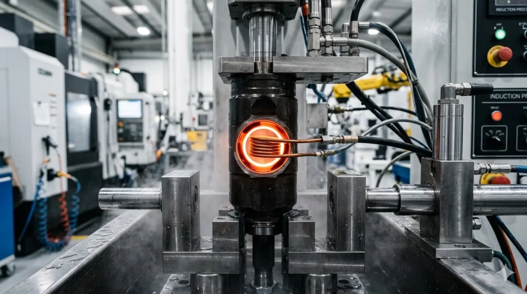
Internal bore induction hardening is among the most demanding areas of induction hardening practice. Unlike external surface hardening, the physics are fundamentally less favorable: magnetic flux lines distribute on the outside of the coil, and heating relies on a reflected magnetic field — inherently less efficient. The confined space inside a bore further restricts inductor design options, making inductor engineering the central technical challenge of the entire process.
Table of Contents
1. Typical Parts and Material Range
Internal bore induction hardening applies to a broad range of components across automotive, construction machinery, and industrial equipment manufacturing. Common examples include internal splines for new energy vehicle drivelines, tripod housing internal splines, engineering machinery spacers, concrete pump tubes, and automotive wheel hub bearing outer rings.
Bore diameters typically range from 12 mm to 200 mm, with materials including 45 steel, S55C, 40Cr, 42CrMo, and 65Mn. Behind this variety of parts lies a shared process challenge: how to design an inductor that delivers sufficient heating efficiency and accommodates a workable quench cooling layout within the confined bore space.
This is fundamentally different from external surface hardening — such as shaft induction hardening or drive wheel hardening — where the coil can wrap around the workpiece and direct magnetic flux straight into the surface. In bore applications, every millimeter of inductor cross-section must be carefully justified.
2. Frequency Selection: The Primary Lever for Efficiency
For the inherently low heating efficiency of internal bores, increasing frequency is the only directly effective solution. Internal bore induction hardening requires frequencies above 20 kHz; for smaller bore diameters, power supply frequency should reach 200 kHz or higher.
Higher frequency reduces current penetration depth, concentrating energy at the bore surface and compensating for the reduced efficiency of reflected-field heating. This is the opposite logic from large-diameter external hardening, where lower frequencies are often needed to achieve sufficient case depth. The ASM International Heat Treating Society provides extensive reference data on induction hardening parameters across different geometries and materials. Understanding how induction heating equipment frequency classifications map to application requirements is essential for selecting the right power supply.
The practical rule is straightforward: as bore diameter decreases, frequency must increase. A 15 mm bore may require 200–300 kHz, while a 150 mm bore can be effectively hardened at 30–50 kHz. Getting frequency selection right is the single most important decision in induction heating power selection for bore applications.
3. Inductor Design: Engineering Trade-offs Under Spatial Constraints
Internal bore inductor design involves several mutually constraining factors. Each design decision affects the others, and the confined space leaves little margin for error.
Conductor Wall Thickness
Wall thickness should be minimized — typically 0.3–1 mm — using T2 copper, electrolytic copper, or oxygen-free copper. This maximizes conductivity while preserving space for flux concentrators and cooling channels. Every tenth of a millimeter saved in wall thickness can be allocated to more effective flux concentration.
Flux Concentrator Selection
Flux concentrator choice depends entirely on operating frequency. At lower frequencies (20–50 kHz), silicon steel laminations of 0.15 mm thickness with high-temperature insulating coating on both faces are appropriate. At higher frequencies (100 kHz+), machinable flux concentrators or imported flux paste become the practical alternatives. For detailed material selection guidance, Fluxtrol offers comprehensive technical resources on magnetic flux concentrator materials and their application-specific performance characteristics. A proven engineering solution is to machine a helical groove into a machinable concentrator rod and wind the coil into the groove — optimizing both space utilization and magnetic circuit efficiency in a single structure.
Turn Count and Frequency
Single-turn inductors are generally sufficient at high frequencies. Multi-turn configurations at high frequency can also perform without flux concentrators in some cases, though this depends on bore geometry and required power density.
Quench Cooling Routing
Quench cooling routing is particularly difficult in blind-bore components, where water lines cannot exit from the bore end. A practical solution for single-shot hardening is to introduce quench fluid directly from above the bore opening, using gravity to assist drainage. For through-bore components, more conventional multi-channel arrangements are feasible.
4. CVJ Outer Race: A Detailed Bore Hardening Case Study
The constant velocity joint (CVJ) outer race is a representative example that illustrates nearly every challenge in internal bore induction hardening. The bore includes an inner cylindrical surface and ball tracks — a complex geometry that demands precise heat distribution. Material is typically Cf53, with a hardness requirement of 58–62 HRC and case depth of 2.5–3.5 mm.
Scanning Hardening Approach
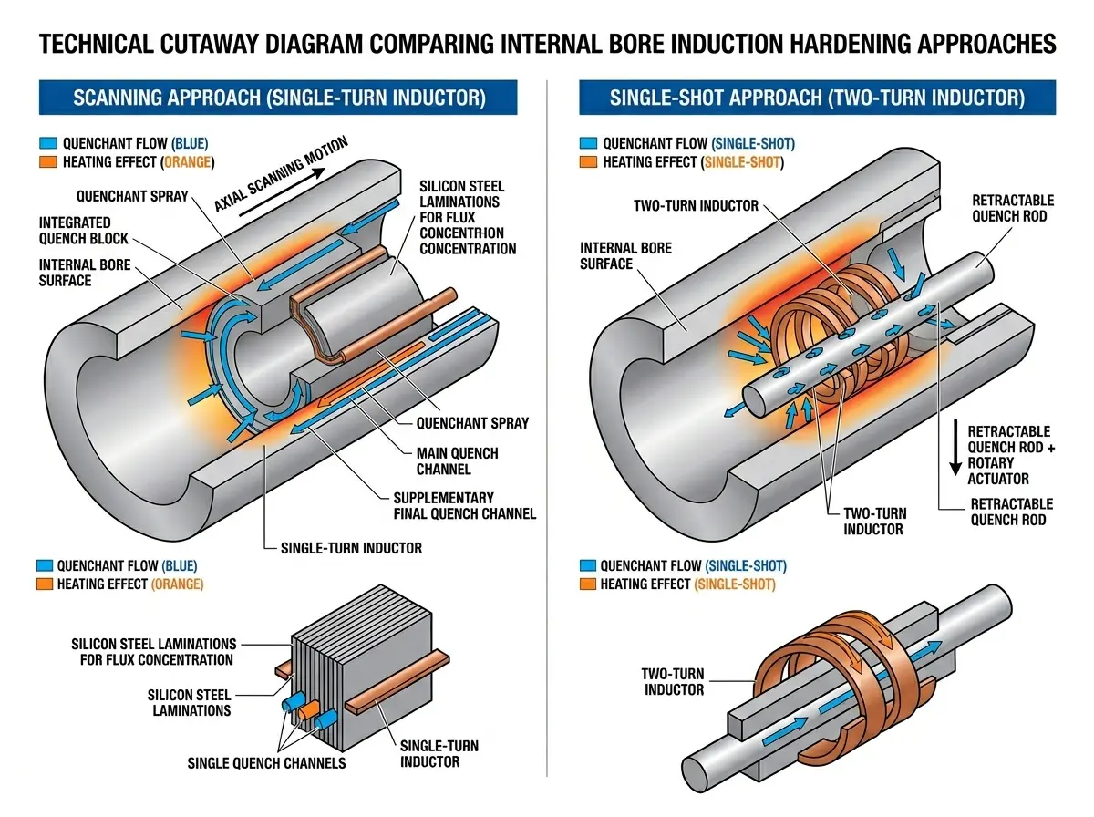
The workpiece is clamped at the shaft end with the bore opening facing downward. A single-turn inductor with 0.15 mm double-faced high-temperature insulated silicon steel laminations is used. Three independent quench water channels are required: an external protective water flow to prevent overheating of the bore rim, a main quench flow for primary cooling, and a supplementary final quench to ensure uniform case depth distribution. The timing sequence of these three channels is critical — mis-timing even one channel can produce uneven case depth or soft spots.
Single-Shot Hardening Approach
The single-shot approach uses a two-turn inductor, with the quench nozzle designed on a retractable rod that withdraws after quenching — a configuration well-suited for integration into automated production cycles. While faster in cycle time, this method requires more complex inductor coverage design and tighter quench timing control.
Comparing the Two Approaches
Scanning hardening places higher demands on inductor manufacturing precision but tends to produce more uniform case depth — a decisive advantage in high-volume production where consistency is paramount. Single-shot hardening is faster in cycle time but requires more sophisticated inductor coverage design and quench timing control. The choice between them depends on production volume, bore geometry, and the acceptable tolerance band on case depth.
For additional guidance on process-specific hardening challenges, refer to our analysis of common gear induction hardening defects — many of the principles around frequency selection and quench design apply equally to bore applications.
🔑 Key Takeaway
The process logic of internal bore induction hardening can be stated succinctly: use high frequency to compensate for the inherent efficiency disadvantage of reflected-field heating, use precise inductor design to work within severe spatial constraints, and use multi-channel quench cooling to achieve uniform case depth.
Bore diameter, geometry (through-bore or blind bore), hardness requirements, and case depth specification together determine the specific combination of frequency, inductor structure, and cooling arrangement. There is no universal standard solution — each part type requires its own targeted design and process qualification.
Frequently Asked Questions
Q: Why is internal bore induction hardening more difficult than external surface hardening?
Two reasons. First, magnetic flux lines naturally distribute on the outside of the coil — heating a bore relies on a reflected magnetic field, which is inherently less efficient. Second, the confined space inside a bore severely restricts inductor size, forcing difficult engineering trade-offs between conductor thickness, flux concentrator volume, and cooling channel routing.
Q: What frequency is needed for internal bore induction hardening?
Internal bore hardening requires frequencies above 20 kHz at minimum. For smaller bore diameters (under 30 mm), power supply frequency should reach 200 kHz or higher. As a practical rule: smaller bore = higher frequency. A 15 mm bore may need 200–300 kHz, while a 150 mm bore can be hardened effectively at 30–50 kHz.
Q: Scanning vs single-shot hardening — which is better for internal bores?
Neither is universally better. Scanning hardening produces more uniform case depth but demands higher inductor manufacturing precision. Single-shot hardening is faster in cycle time and suits automated production, but requires more complex inductor coverage design and tighter quench timing control. The right choice depends on part geometry, volume, and tolerance requirements.
Q: What flux concentrator material should I use for bore inductors?
At lower frequencies (20–50 kHz), 0.15 mm silicon steel laminations with high-temperature insulating coating work well. At higher frequencies (100 kHz+), machinable flux concentrators or flux paste are preferred. A common solution is machining a helical groove into a machinable concentrator rod and winding the coil into the groove for optimal space efficiency.
Need Bore Hardening Process Support?
Contact our engineering team for application-specific guidance on internal bore inductor design, frequency selection, and process qualification. We respond promptly with a technical assessment.


