
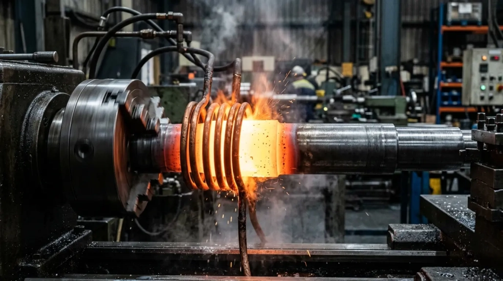
Mastering Shaft Induction Hardening: 3 Critical Quality Challenges from Diameter to Cracking Control
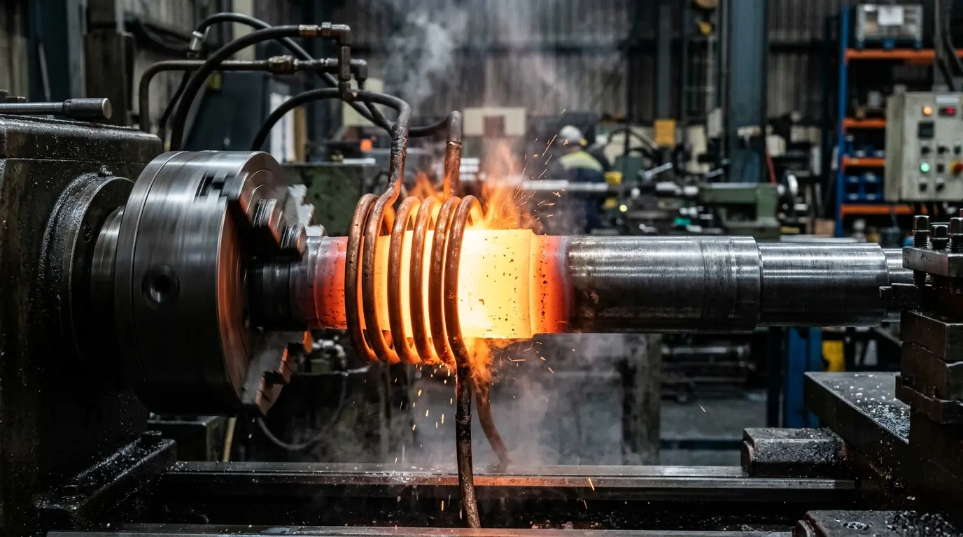
Shaft induction hardening spans one of the widest process windows in the industry — from 6 mm micro motor shafts to 460 mm new energy drive axles, from plain carbon steel to 42CrMo alloy steel, with case depth requirements ranging from 0.8 mm to over 10 mm. Getting it right means mastering three dimensions: frequency vs. diameter matching, systematic cracking root-cause analysis, and process sequencing for complex geometries. This article covers all three, with practical decision frameworks for each.
📋 Table of Contents
1. Classification by Diameter: Frequency and Inductor Selection
In shaft induction hardening, frequency is the primary process parameter, and its selection is directly tied to workpiece diameter. Understanding the frequency classification of induction heating equipment is the essential starting point for any process design.
Shafts Under 20 mm: 200–600 kHz
For small-diameter shafts, the recommended frequency is 200–600 kHz. A typical example is a 6 mm motor shaft in 40Cr steel requiring a case depth of 0.8–1.2 mm. A single-turn inductor with scanning hardening is the standard configuration. An 8 mm miniature ball screw follows the same approach. Alloy tool steel shafts around 18 mm in diameter are also candidates for single-shot hardening — the small diameter means the entire circumference can be heated uniformly in one shot.
Shafts 20–100 mm: 2–15 kHz
For medium-diameter shafts, frequency narrows to 2–15 kHz. A dual-turn inductor is the common choice, with scanning or single-shot modes selected based on the required case depth. This diameter range covers the bulk of general industrial shaft components, and correct power selection in this band is critical — undershooting the power supply capacity leads to insufficient case depth, while overshooting wastes capital and energy.
Shafts Above 100 mm: 2–6 kHz
For large-diameter shafts exceeding 100 mm, frequency drops to 2–6 kHz, and a single-turn self-quench scanning inductor is preferred. Where deeper case depths are demanded, preheating the workpiece before hardening can extend the effective hardened depth. The low frequency ensures sufficient current penetration to reach the required depth, while the self-quench design simplifies the cooling circuit.
This classification is straightforward in principle, but many quality failures in practice come directly from a mismatch between frequency and diameter. Too high a frequency results in insufficient current penetration and a case too shallow to meet requirements. Too low a frequency causes heat to diffuse excessively toward the core, widening the transition zone between hardened case and soft core — neither condition is acceptable for a service-critical shaft.
2. Truck Drive Shafts: A Systematic View of Cracking
Truck rear axle shafts are among the most failure-prone shaft types in induction hardening. Batch cracking incidents are not uncommon, and they tend to surface only at the claims stage — a symptom of root-cause analysis that has historically been insufficient. Unlike the straightforward frequency-diameter relationship in Section 1, cracking in shaft induction hardening typically involves multiple compounding factors operating simultaneously.
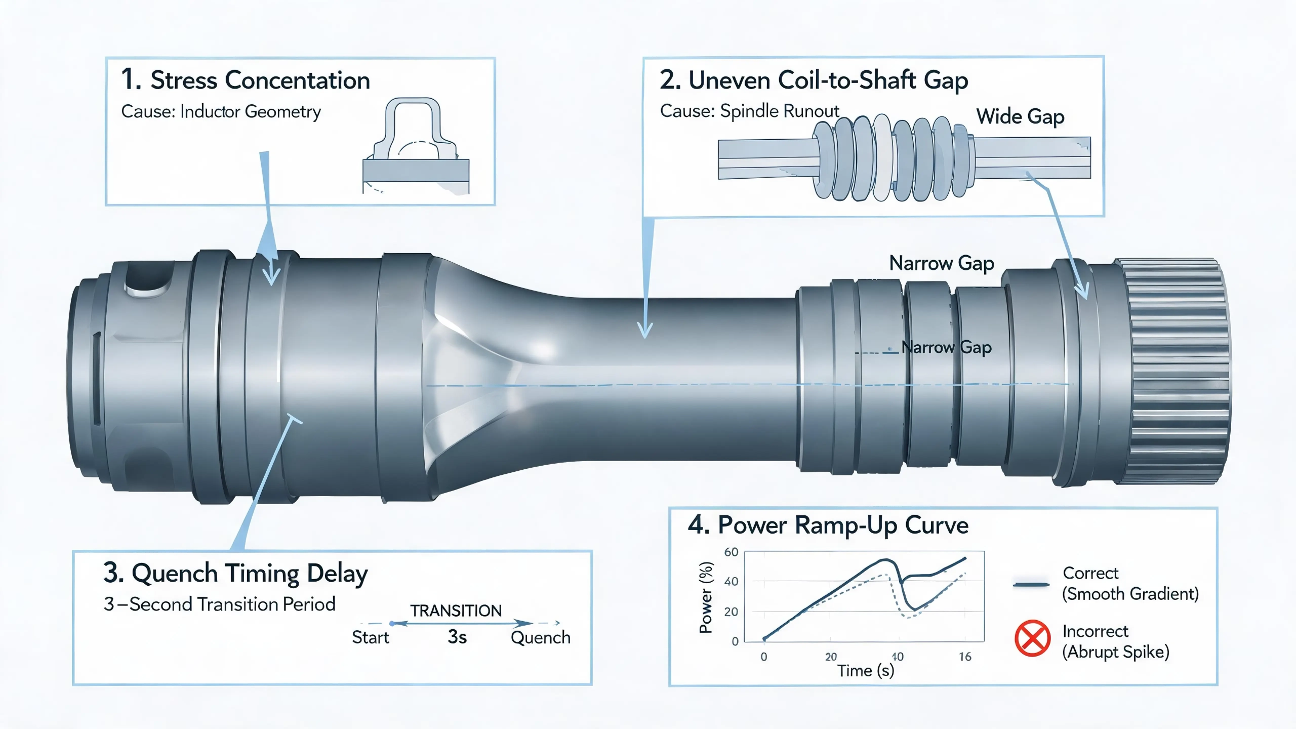
Cause 1: Inductor Design Deficiencies
This is the leading factor. Controlling case depth at the chassis fillet radius is technically demanding, and poor inductor geometry leads directly to stress concentration at the most fatigue-sensitive location on the shaft.
The flux concentrator — an integral part of the inductor assembly — requires specific attention: silicon steel laminations should be 0.15 mm thick with high-temperature insulating coating on both faces. If the insulation degrades during heating, the laminations themselves heat up, lose magnetic permeability, and compromise the uniformity of local heating. What starts as an insulation failure at one lamination can cascade into uneven hardening across the entire fillet zone.
Cause 2: Inadequate Equipment Precision
Excessive spindle runout reduces the gap between the workpiece and inductor at certain rotational positions, creating localized overheating or even surface melting. This is a machine maintenance issue that is often overlooked because it develops gradually — the gap drift over weeks of operation may not trigger alarms until parts start failing inspection. Regular spindle runout checks should be part of the preventive maintenance schedule for any shaft hardening cell.
Cause 3: Improper Quench Cooling
PAG quench medium is recommended at a concentration above 10%, with fluid temperature maintained at 30–35 °C. However, the most common quench-related cracking cause is not the medium itself — it is the timing. Full-flow quenching should not begin immediately at the start of the cooling stage. A controlled delay followed by a low-flow initial phase — transitioning to full flow after approximately 3 seconds — is necessary to suppress the surface tensile stress spike that triggers quench cracking. This 3-second window is narrow and unforgiving.
Cause 4: Incorrect Process Parameters
Power should be ramped up gradually at the start of the scan — an instantaneous jump to full power creates a thermal shock at the shaft end. The end-of-scan deceleration should not be excessive, as a slow exit can over-temper the starting zone. Frequency selection must also match the material grade: alloy steels like 42CrMo require different frequency-power combinations than plain carbon steels at the same diameter.
These four causes are not independent. Batch cracking events typically involve multiple issues compounding simultaneously — an inductor geometry issue combined with spindle runout and suboptimal quench timing, for example. This is precisely why systematic investigation — rather than singling out one factor — is the only reliable approach. For a broader perspective on process selection across different gear and shaft geometries, see our comparison of single-shot vs. tooth-by-tooth induction hardening for drive wheels.
3. New Energy Motor Shafts: Process Sequencing for Complex Geometry
New energy drive motor shafts represent the higher end of complexity in shaft induction hardening. A typical component is approximately 460 mm in length, with an external spline at one end, an internal spline at the other, multiple diameter transitions along the shaft body, full surface hardening required on all external diameters, and hardening also required on the internal spline.
External Surface Hardening
Full-length single-shot hardening can cover all external diameter transitions in one operation. This approach demands substantial power — a 500 kW induction power supply is the appropriate scale for a shaft of this size. Single-shot processing also minimizes the thermal distortion that would accumulate across multiple scanning passes.
Critical Sequencing Rule: Internal Before External
Internal spline hardening must be completed before external surface hardening. This sequence is not negotiable. After external hardening, the thermal conditions in the bore change — the external hardened layer alters the thermal mass distribution and cooling behavior of the entire component. If internal spline hardening follows external hardening, the bore thermal profile becomes unpredictable, and the internal spline hardening result will be inconsistent from part to part. Reversing the sequence eliminates this variable entirely.
Managing Diameter Transitions
The geometry of diameter transitions adds a further layer of complexity. Different diameter sections require different power densities. When scanned at constant parameters, the transition zones tend to produce uneven case depth distribution — the larger diameter section receives less power density, while the smaller section may overheat.
Components of this type require careful stage-by-stage verification of case depth and hardness distribution during process qualification. Cross-section the shaft at each diameter transition, measure the hardness profile, and adjust the power program accordingly. The investment in upfront qualification pays back in avoiding batch-level non-conformance discovered only at final inspection.
Key Takeaway
The core discipline in shaft induction hardening is establishing the correct relationship between diameter, frequency, and inductor design, then refining that foundation for the specific material and geometry of each part. Cracking, insufficient case depth, and non-uniform hardening at diameter transitions are the three most common quality problems in this category. Their causes differ, but the root in nearly every case traces back to either inductor design or process parameter selection — not to a need for more expensive equipment.
For practical guidance on a closely related topic — how to handle non-martensitic structures and distortion in gear components — see our article on solving non-martensitic structure and distortion in gear induction hardening.
FAQ: Common Questions About Shaft Induction Hardening
Q1: How do I choose the right frequency for my shaft diameter?
The rule of thumb: shafts under 20 mm use 200–600 kHz, 20–100 mm use 2–15 kHz, and above 100 mm use 2–6 kHz. But the more precise answer depends on your required case depth. Higher frequency concentrates current near the surface (shallow case), while lower frequency penetrates deeper. Match frequency to your specified case depth first, then select power to achieve the required heating time. For a detailed breakdown, refer to our guide on frequency classification of induction heating equipment.
Q2: What is the most common cause of axle shaft cracking in induction hardening?
There is no single “most common” cause — and that is itself the key insight. Batch cracking is almost always multi-factor: inductor geometry creates a stress concentration, spindle runout amplifies it, quench timing adds a thermal stress spike, and power ramp-up parameters fail to compensate. The danger is singling out one factor, “fixing” it, and assuming the problem is solved. A systematic investigation covering all four cause categories — inductor design, equipment condition, quench cooling, and process parameters — is the only reliable approach.
Q3: Why must internal spline hardening precede external surface hardening on motor shafts?
Once the external surface is hardened, the martensitic layer changes the thermal mass and heat extraction behavior of the entire shaft. If you then attempt to harden the internal spline, the bore thermal profile becomes unpredictable — the external hardened layer acts as a heat sink in some regions and an insulator in others, depending on geometry. The result is inconsistent internal spline hardness from part to part. Hardening the internal spline first eliminates this variable entirely, because the external surface is still in its annealed, thermally predictable state during the internal operation.
Q4: What power supply capacity do I need for shaft induction hardening?
It depends entirely on your shaft diameter, production rate, and case depth requirement. Small-diameter shafts (under 20 mm) with scanning hardening may only need 50–100 kW. Medium shafts (20–100 mm) with dual-turn scanning typically require 100–250 kW. Large shafts or single-shot processing of complex geometries can demand 500 kW or more. The critical mistake is undersizing — compensating for insufficient power by extending heating time drives heat into the core and produces an oversized transition zone. If you are unsure about your specific requirement, see our induction heating power selection guide or consult our engineering team with your part specifications.
Contact Us for a Free Process Evaluation
If you are dealing with cracking, case depth inconsistency, or process design challenges in your shaft induction hardening line, our engineering team can provide a free process evaluation. Submit your inquiry with your workpiece drawing, material grade, and current process parameters, and we will deliver a preliminary diagnosis and optimization proposal within 48 hours — covering frequency selection, inductor design recommendations, quench system configuration, and process sequencing for complex shaft geometries.
Take the next step: share your part print and production requirements. Our application engineers will analyze your process bottlenecks at no cost and recommend targeted fixes — whether that means inductor geometry optimization, quench timing adjustment, spindle maintenance scheduling, or a complete process re-sequence for multi-feature shafts. Visit our knowledge center for more technical resources on induction hardening applications across the automotive industry.


