
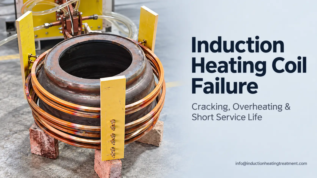
유도 가열 코일이 실패하는 이유: 균열, 과열 및 짧은 서비스 수명
Common Coil Failure Mechanisms and What to Check Before Premature Replacement
Induction heating coils are exposed to high electrical currents, repeated thermal cycling and mechanical stresses. Some operate reliably for extended periods, while others develop cracks, cooling-water leaks or localized damage much earlier than expected.
Premature induction heating coil failure may involve thermal fatigue, 불충분한 냉각, electrical arcing, mechanical loading or weaknesses in coil construction. These mechanisms can produce similar visible damage, making the underlying cause difficult to identify from appearance alone.
Understanding how coils fail — and what to examine before replacing them — can help prevent the same problem from recurring.
2. Why Coils Overheat, Burn Through or Develop Water Leaks
3. How to Interpret Different Types of Coil Damage
4. How to Investigate Premature Induction Coil Failure
1. Why Induction Heating Coils Crack
Many industrial 유도 코일 are manufactured from copper tubing or specially shaped copper conductors, often with internal passages for water cooling.
Copper provides high electrical and thermal conductivity, but the coil still experiences temperature changes, electromagnetic forces and mechanical loading during operation.
Cracks can develop when these stresses repeatedly concentrate in vulnerable areas.
Thermal fatigue and repeated heating cycles
An induction coil generates heat through electrical resistance and receives additional heat from the nearby workpiece. Water cooling removes much of this heat, but the temperature may not be uniform throughout the conductor.
Regions operating at different temperatures expand and contract by different amounts. Repeated thermal cycling can gradually produce fatigue damage, particularly where expansion is restrained or local stresses are concentrated.
Bends, conductor transitions and brazed joints may be susceptible, depending on their geometry and operating conditions.
A fatigue crack can develop progressively before becoming visible or eventually penetrating a water passage.
그러나, a crack near a bend does not automatically prove thermal fatigue. Mechanical loading, corrosion and manufacturing-related stresses may produce similar damage.
Current concentration and localized copper heating
The alternating current in an induction coil is not distributed uniformly across the conductor.
Skin effect, proximity effect and coil geometry influence current density. Certain conductor edges and transitions may experience concentrated current and higher local electrical losses.
If local heat generation exceeds the cooling available at that location, the copper temperature can increase. Repeated thermal stresses may then contribute to cracking.
Inductoheat examines this mechanism in Coil Failure: Electromagnetic Edge Effect, discussing how conductor geometry, frequency and current distribution influence coil life and crack development.
The presence of an edge or sharp transition does not establish that current concentration caused a particular failure. The actual electrical and thermal conditions need to be evaluated.
Mechanical vibration, restraint and impact
Mechanical loading can initiate or accelerate damage independently of local overheating.
Vibration may repeatedly stress copper conductors and joints, especially near unsupported sections or rigid connections. Thermal expansion can introduce additional stress when the coil assembly is excessively restrained.
Accidental contact between the workpiece and inductor is another possible cause.
A collision during loading, rotation or scanning may deform the conductor, damage insulation or create a weakness that later develops into a crack.
When cracking appears near supports, mounting points or workpiece-facing surfaces, the mechanical arrangement deserves as much attention as the heating conditions.
2. Why Coils Overheat, Burn Through or Develop Water Leaks
Localized overheating is a significant cause of induction coil damage. It can weaken copper, contribute to thermal fatigue and, under severe conditions, cause melting or loss of conductor integrity.
The problem may originate from excessive local heat generation, inadequate heat removal or a combination of both.
Local cooling problems
A water-cooled induction coil depends on coolant circulation through its internal passages.
If a passage becomes restricted or its geometry provides inadequate heat removal, the copper surrounding that area may operate at a higher temperature than intended.
Possible contributing factors include deposits, debris, poorly formed passages and restrictions near joints or changes in conductor geometry.
A normal reading from the main cooling-water supply does not necessarily establish that every part of the coil is being cooled adequately. Flow distribution and local heat transfer also matter.
에서 Best Practice for Design and Manufacturing of Heat Treating Inductors, Fluxtrol examines a specific CVJ stem-hardening inductor in which local copper overheating was associated with the conductor geometry and cooling arrangement.
The paper discusses thermal-fatigue cracking, local melting and the influence of cooling-passage design. Its findings illustrate how local coil conditions can govern service life, rather than establishing a universal failure mechanism for every inductor.
Broader cooling-system design, water quality and maintenance issues are covered in 유도가열 수냉식 시스템.
Electrical arcing and local melting
Arcing can cause severe localized damage to an induction coil.
Depending on the electrical arrangement, insulation condition and clearances, an arc may develop between conductive parts of the coil assembly or between the coil and workpiece.
Possible contributing conditions include damaged insulation, unintended contact, incorrect positioning and insufficient electrical separation.
Arcing can leave concentrated erosion, surface damage or melted copper.
These signs are useful during inspection, but local melting is not conclusive proof of arcing. Severe overheating caused by electrical losses and inadequate cooling may also damage the conductor.
The surrounding insulation, conductor clearances and evidence of contact should be examined before assigning a cause.
Why cooling-water leaks occur
A water leak may be the final result of damage that developed over many production cycles.
Common possibilities include fatigue cracks penetrating the conductor wall, deterioration or defects at brazed joints, corrosion-related damage and mechanical impact.
Severe overheating or arcing may also compromise a cooling passage.
The leak location can help narrow the investigation. 예를 들어, repeated leakage near a joint may suggest a recurring stress, joint-construction or corrosion problem.
그러나, leakage at a brazed connection does not establish that the brazing process was defective. Loads imposed during installation or operation may also contribute.
In induction hardening systems with integrated spray quenching, liquid near the inductor should first be traced to its source. Water from the quench arrangement is not necessarily evidence of a leaking coil.
A coil with suspected leakage, severe conductor damage or compromised insulation must not remain energized. Electrical power and other hazardous energy sources should be isolated according to the equipment manufacturer’s procedures before qualified personnel inspect the assembly.
3. How to Interpret Different Types of Coil Damage
The location and appearance of damage provide clues, but they rarely identify the root cause independently.
A crack may follow repeated thermal cycling or mechanical loading. Discolored copper may have experienced elevated temperatures without necessarily suffering structural failure. A melted area may result from arcing or inadequate local cooling.
The following observations can guide an initial investigation.
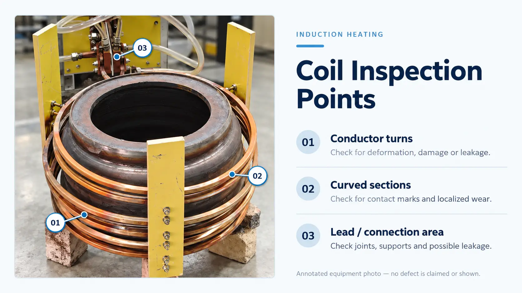
| Observed Damage | Possible Contributing Factors | 초기 조사 |
|---|---|---|
| Cracks near bends or conductor transitions | Thermal fatigue, mechanical stress, local current concentration | Crack location, conductor geometry, cooling and mechanical restraint |
| Leakage at brazed joints | Joint defects, fatigue, corrosion or external loading | Joint condition, support arrangement and previous leak history |
| Local discoloration or copper deformation | Elevated copper temperature, concentrated electrical losses or insufficient cooling | Local cooling conditions, operating history and conductor geometry |
| Concentrated erosion or melted spots | Electrical arcing or severe localized overheating | 절연, electrical clearances and evidence of workpiece contact |
| Bent or displaced conductors | Mechanical impact, vibration or excessive thermal loading | 공작물 이동, loading clearance and mounting condition |
가능한 조사 방향은 다음과 같습니다., not confirmed diagnoses.
Why repeated failures at the same location matter
If successive coils fail at approximately the same location, the pattern may indicate a recurring influence associated with the application, design or operating conditions.
For instance, repeated cracking near a support may justify examining mechanical restraint and vibration. Repeated overheating at one conductor transition may warrant reviewing local current distribution and cooling.
The final visible damage may also be secondary to an earlier problem.
A local cooling restriction could contribute to overheating, followed by fatigue damage and eventual leakage. In such a case, repairing the crack alone would not address the original cause.
Copper conductor damage versus accessory damage
Some inductors incorporate magnetic flux concentrators, insulation and protective components.
Damage to these parts should be distinguished from failure of the copper conductor.
A cracked flux concentrator does not necessarily mean that the coil’s cooling passage or copper structure has failed. 반대로, an apparently intact conductor does not establish that the complete inductor assembly remains suitable for operation.
Flux concentrator damage has its own material and operating considerations, discussed in 유도 가열 코일용 자기 플럭스 농축기.
4. How to Investigate Premature Induction Coil Failure
Replacing a damaged coil may restore production, but repeated failures require a closer examination of the conditions under which the coil operates.
The investigation should begin with the failed component and its operating history, rather than immediately changing power settings or modifying the coil design.
Practical troubleshooting checklist
After the equipment has been safely shut down and isolated, qualified personnel can use the following checks to guide the investigation.
☐ Document the damage. Record the exact location of cracks, 누수, melted areas, discoloration or deformation. Photograph the failed assembly before repair.
☐ Review the cooling conditions. Check available coil-circuit flow, 압력, temperature and maintenance records. Investigate possible restrictions or changes in cooling performance.
☐ Inspect mechanical clearances. Look for evidence of workpiece contact, 진동, displaced supports or unintended loading during operation.
☐ Examine electrical damage. Check insulation condition, conductor separation and visible arc marks. Do not assume that every melted area was caused by arcing.
☐ Compare operating conditions. Review actual power, 주파수, duty cycle and relevant process changes before the failure.
☐ Check previous failures. Determine whether earlier coils failed at similar locations or under similar production conditions.
☐ Verify repair and return-to-service requirements. Have qualified personnel establish that the repaired or replacement assembly meets the applicable integrity, electrical safety and operating requirements before restarting.
The checklist helps identify where further investigation is needed. It does not replace a detailed failure analysis when the mechanism remains uncertain.
Distinguishing operating problems from coil-design problems
Some failures may be associated with conditions that changed during production.
Examples include reduced cooling performance, a modified duty cycle, workpiece misalignment or a new mechanical loading condition.
Other failures may be related to the conductor geometry, copper material, cooling-passage layout, brazed-joint construction or support arrangement.
Where repeated damage occurs despite apparently unchanged operating conditions, a review of the coil’s construction and local thermal loading may be necessary.
Inductoheat’s Coil Failure: Coil Copper Selection discusses how copper properties and mechanisms such as stress-fatigue cracking, stress-corrosion cracking and galvanic corrosion can affect inductor reliability.
These mechanisms require supporting evidence. Corrosion should not be diagnosed solely from surface discoloration, nor should every fatigue crack be attributed to unsuitable copper.
If the cause remains unclear, examination of the damaged conductor, fracture region or brazed joint may be needed.
How long should an induction heating coil last?
There is no reliable universal service-life figure for induction heating coils.
Lifetime depends on the coil type, 설계, manufacturing quality, operating conditions and the stresses imposed during production.
Some applications require frequent tooling replacement, while others achieve much longer service intervals.
In the ASM Heat Treat 2023 conference paper How Long Should My Induction Coil Last?, Aaron Goodwin of Inductoheat discusses the influence of coil design, process parameters and application-specific features on service life.
The paper emphasizes that the number of interacting factors makes accurate general lifetime predictions difficult.
For production maintenance, recorded operating history is more useful than an unsupported replacement interval. Tracking the failure location, type of damage, operating conditions and service history can reveal patterns that would otherwise be missed.
The objective of induction coil failure investigation is not simply to identify a damaged component. It is to determine whether the damage arose from a recurring thermal, 전기 같은, mechanical or construction-related condition.
Replacing a coil without addressing the underlying mechanism may restore operation temporarily while leaving the next coil exposed to the same failure.
핵심 내용: Induction coil damage that looks similar can arise from different causes — thermal fatigue, 불충분한 냉각, 스파크가 발생하고 있다, mechanical loading or construction weaknesses. Investigate the failure location and operating history before replacement, so the next coil is not exposed to the same mechanism.
자주 묻는 질문
답변을 펼치려면 질문을 클릭하세요..
Does a crack near a bend prove thermal fatigue?
아니요. A crack near a bend can also result from mechanical loading, corrosion or manufacturing-related stresses. The crack location, conductor geometry, cooling and mechanical restraint need to be examined before assigning a cause.
Is a melted area on the coil always caused by arcing?
아니요. Arcing produces concentrated erosion and melted spots, but severe local overheating from electrical losses and inadequate cooling can also damage the conductor. Insulation condition, clearances and evidence of contact should be examined before attributing melting to arcing.
Can the failure cause be identified from the coil’s appearance alone?
Rarely. 균열, discoloration and melted areas provide clues about where damage occurred, but similar visible damage can arise from different mechanisms. The location, operating history and supporting evidence are needed to distinguish between thermal, 전기 같은, mechanical and construction-related causes.
Is there a fixed replacement interval for induction heating coils?
아니요. Coil life depends on the coil type, 설계, manufacturing quality, operating conditions and the stresses imposed during production. Tracking failure location, damage type and operating history is more useful than an unsupported replacement schedule.
Need help diagnosing an induction coil failure?
Send details of the coil damage, operating conditions and failure history, and we can help identify the underlying cause.


