
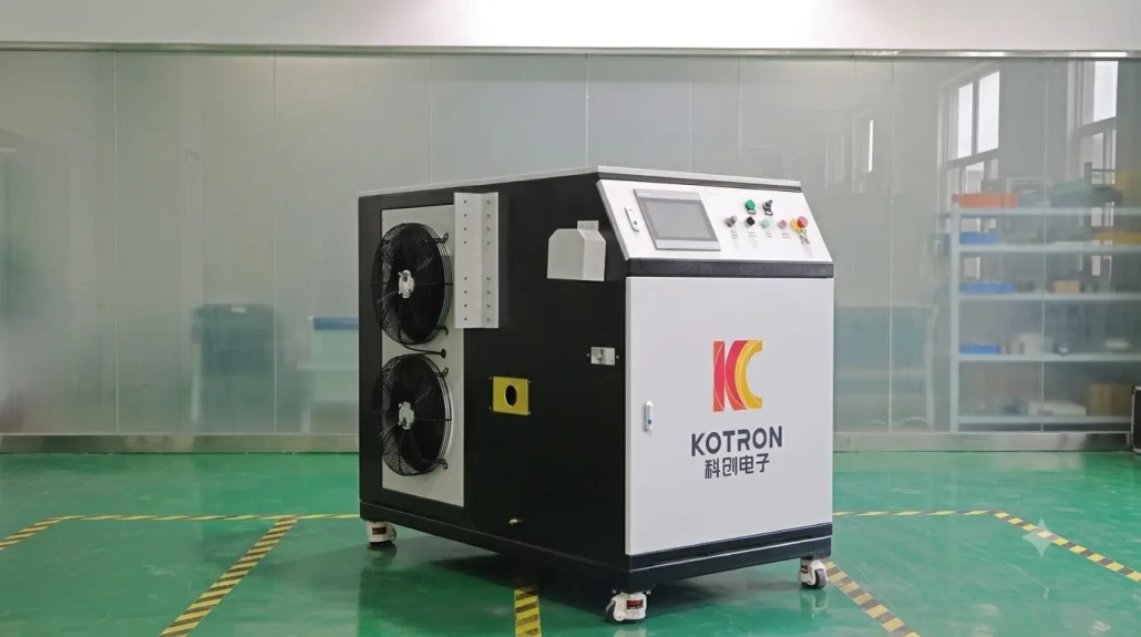
Induction Heating Water Cooling System: The Complete Guide to Sizing, Design & Maintenance
Every induction heating machine — whether a 15 kW benchtop unit or a 500 kW production line — converts some of its input power into heat that never reaches the workpiece. This waste heat builds up in the power electronics, the capacitors, and most critically, the induction coil itself. Without an effective induction heating water cooling system, your machine either shuts down on thermal overload or cooks its own components to failure. This guide walks through everything you need to size, design, and maintain a water cooling system that keeps your induction equipment running at full power — shift after shift.
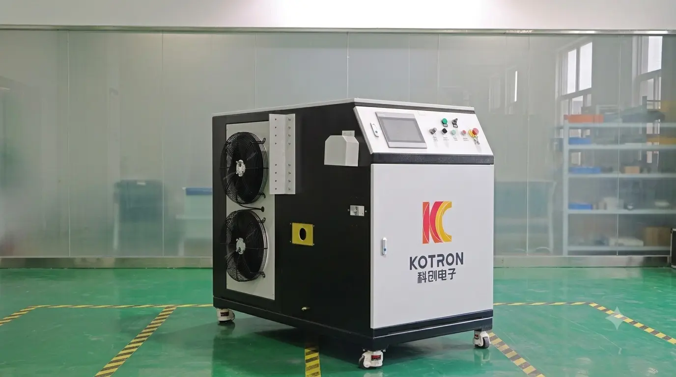
Table of Contents
- Why Water Cooling Matters — Understanding the Heat Load
- Closed-Loop vs. Open-Loop: The 5 Critical Differences
- How to Calculate Your Cooling Capacity
- Water Quality: The Hidden Variable That Kills Systems
- Key Components: What Goes Into a Reliable System
- Common Problems & Troubleshooting
- Summary & Quick Reference
1. Why Water Cooling Matters — Understanding the Heat Load
An induction heating system is not 100% efficient. Depending on the power supply design and operating frequency, 15% to 35% of the input electrical power is converted to waste heat rather than useful workpiece heating. This waste heat comes from three main sources: I²R losses in the copper coil (resistive heating), switching losses in the IGBT or SCR power modules, and dielectric losses in the tank capacitors. For a 100 kW induction heater operating at 80% efficiency, that means 20 kW of heat must be continuously removed — equivalent to seven household electric kettles boiling nonstop inside your equipment cabinet.
If this heat is not removed, the consequences escalate quickly. Copper coil resistance increases with temperature, further reducing efficiency and creating a thermal runaway feedback loop. IGBT modules derate above 85°C junction temperature and fail outright above 125°C. Capacitors lose capacitance and develop internal shorts. A properly sized induction heating water cooling system prevents all of this by maintaining component temperatures within their rated operating range — typically 25–35°C coolant inlet temperature for power electronics and 30–45°C for coil cooling circuits. For more on how coils generate and handle thermal loads, see our guide on how induction coils work.
2. Closed-Loop vs. Open-Loop: The 5 Critical Differences
The most fundamental design decision for any induction heating water cooling system is whether to run closed-loop (recirculating) or open-loop (once-through, or tower-based). Each approach has fundamentally different cost, reliability, and water quality implications.
Closed-Loop Systems. The coolant circulates in a sealed loop: reservoir → pump → induction equipment → heat exchanger (inside a chiller or cooling tower) → back to reservoir. The same water recirculates indefinitely. Because the water never contacts the outside environment, its chemistry can be precisely controlled — typically deionized or distilled water with corrosion inhibitors. This is the standard choice for industrial induction heating and the only recommended approach for equipment above 30 kW.
Open-Loop Systems. Water flows through the induction equipment once and is then discharged to drain or returned to a cooling tower basin. This is simpler and cheaper to install — no chiller, no heat exchanger, just a supply line and a drain — but the water quality is whatever comes out of the municipal supply or the cooling tower. Minerals deposit on hot surfaces as scale. Dissolved oxygen promotes corrosion. Biological growth clogs narrow cooling channels. For equipment below 15–20 kW with generous cooling channels and intermittent duty cycles, open-loop can work. For anything else, the long-term maintenance cost outweighs the upfront savings.
| Factor | Closed-Loop | Open-Loop |
|---|---|---|
| Water quality control | Full control — deionized water, inhibitor additives | None — subject to supply chemistry, seasonal variation |
| Scaling risk | Near-zero — no mineral replenishment | High — minerals continuously deposited on hot surfaces |
| Corrosion risk | Low — controlled chemistry, inhibitors | Moderate to high — dissolved oxygen, variable pH |
| Upfront cost | Higher — chiller/heat exchanger, pump, reservoir | Lower — only supply plumbing and drain |
| Operating cost | Chiller power consumption + inhibitor replenishment | Continuous water consumption + discharge fees |
| Recommended for | All industrial systems above 30 kW; production environments | Low-power (<20 kW), intermittent use, lab/prototype only |
3. How to Calculate Your Cooling Capacity
Sizing a cooling system begins with a simple formula. For a modern solid-state induction power supply with IGBT-based inverter, assume 20–25% of the rated output power must be removed as waste heat. Older SCR-based systems run closer to 30–35%. The cooling capacity in kilowatts is:
Cooling kW = Rated Output kW × Waste Heat Percentage
Example: A 100 kW induction heater with a modern IGBT power supply (22% losses) needs 22 kW of cooling. A 50 kW SCR unit (30% losses) needs 15 kW.
Add a 20% safety margin to account for high ambient temperatures, degraded chiller performance over time, and worst-case duty cycles. The 100 kW example above would spec a chiller rated for at least 26.4 kW (round up to 30 kW). If you are unsure about your machine’s actual power consumption and losses, see our guide on how much power you need for induction heating — the power sizing logic feeds directly into cooling system requirements.
Flow Rate Calculation. Once you have the cooling load, flow rate follows from the temperature rise you are willing to allow across the equipment. The standard rule: a ΔT of 5–8°C between inlet and outlet is the sweet spot — tight enough for stable cooling, loose enough that a standard chiller pump can deliver the flow. The formula:
Flow Rate (L/min) = (Cooling kW × 60) ÷ (4.18 × ΔT)
For the 100 kW / 22 kW cooling example with a 6°C ΔT: Flow = (22 × 60) ÷ (4.18 × 6) = 52.6 L/min. This means the pump must deliver approximately 53 L/min at the required head pressure to overcome piping, coil, and heat exchanger resistance. Always verify that both the chiller pump and the equipment’s internal cooling circuit can handle the calculated flow rate.
| Induction Heater Power | Waste Heat @ 22% | Chiller Size (with 20% margin) | Flow Rate @ ΔT=6°C | Typical Application |
|---|---|---|---|---|
| 15 kW | 3.3 kW | 5 kW (≈1.5 ton) | 8 L/min | Benchtop/lab hardening |
| 50 kW | 11 kW | 15 kW (≈4 ton) | 26 L/min | Small production hardening |
| 100 kW | 22 kW | 30 kW (≈8.5 ton) | 53 L/min | Mid-size production line |
| 200 kW | 44 kW | 55 kW (≈15 ton) | 105 L/min | Large forging/heavy hardening |
| 500 kW | 110 kW | 135 kW (≈38 ton) | 263 L/min | High-volume billet heating |
4. Water Quality: The Hidden Variable That Kills Systems
Water quality is the most overlooked aspect of induction heating water cooling system design — and the most expensive to ignore. Poor water chemistry corrodes copper coils from the inside, deposits scale that insulates heat transfer surfaces, and creates conductive paths that can arc through coolant to ground. Here are the key parameters every operator should monitor:
Electrical Conductivity: < 50 µS/cm. This is the non-negotiable number. Cooling water circulating through an induction coil sits at elevated voltage potential relative to ground. If the water is too conductive, leakage current flows through the coolant — wasting power, generating unnecessary heat in the water itself, and in extreme cases causing electrolytic corrosion that eats pinholes through copper tubing. For high-frequency systems (above 100 kHz), target < 10 µS/cm. Deionized or distilled water with a small amount of glycol-based inhibitor is the standard starting point.
pH: 7.0–8.5. Slightly alkaline is ideal for copper and brass cooling circuits. Below 6.5, acidic conditions attack copper oxide protective layers. Above 9.0, aluminum components (if present in the cooling loop) suffer alkaline corrosion. Test pH monthly; a drifting pH often signals inhibitor depletion or biological contamination.
Total Dissolved Solids (TDS): < 100 ppm. Every dissolved mineral in the water is a potential scale deposit when that water hits a hot surface. Calcium and magnesium carbonates are the worst offenders — they precipitate as hard white scale on coil internal walls and heat exchanger surfaces, reducing heat transfer and eventually blocking flow entirely. In open-loop systems using hard municipal water, TDS can reach 300–500 ppm and scaling becomes a matter of weeks, not months.
Inhibitors & Biocides. Even closed-loop systems need chemical maintenance. A corrosion inhibitor package (typically based on benzotriazole for copper protection plus molybdate or nitrite for ferrous metals) prevents gradual metal loss. A biocide prevents algae and bacteria from colonizing the warm, dark, wet interior of your cooling loop — a problem that manifests as slimy deposits clogging flow switches and narrow coil passages. Most chiller manufacturers sell pre-mixed inhibitor concentrates; follow the recommended dosage and replace annually.
5. Key Components: What Goes Into a Reliable System
A complete induction heating water cooling system for industrial use consists of five core components. Understanding what each one does — and what happens when it fails — helps you spec a system that does not become the bottleneck in your production.
1. Chiller or Cooling Tower. This is the heat rejection device — the component that dumps the waste heat to the outside environment. A chiller (mechanical refrigeration) provides precise temperature control, independent of ambient conditions, and is the standard choice for induction heating. A cooling tower (evaporative) is cheaper to operate at very high heat loads but cannot deliver coolant below the ambient wet-bulb temperature — a problem in hot, humid climates. For most induction shops, an air-cooled chiller sized per the table in Section 3 is the right answer. Specify ±1°C temperature stability if your process involves tight metallurgical control; for general hardening, ±2°C is adequate.
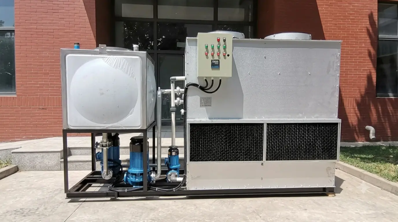
2. Circulation Pump. The pump must deliver the required flow rate at the total system head pressure. For closed-loop systems, a centrifugal pump with stainless steel wetted components is standard. Avoid cast iron pump housings — they rust and contaminate the coolant. The pump should be sized for 100–120% of the calculated flow requirement and capable of maintaining pressure at the equipment inlet (typically 2–4 bar / 30–60 psi). Many induction power supplies have a built-in flow switch that will not permit operation below a minimum flow threshold — verify your pump meets this threshold before commissioning.
3. Reservoir Tank. A buffer tank in the return line serves three purposes: it allows air bubbles to separate from the returning coolant (entrained air drastically reduces heat transfer), it provides thermal mass to dampen temperature fluctuations, and it gives you a convenient fill/inspection point. Size the tank at roughly 10–15% of the total system volume. Use a sealed or vented polyethylene or stainless steel tank — avoid galvanized steel, which reacts with glycol inhibitors.
4. Particulate Filter. A 50–100 micron in-line filter on the return side catches debris before it reaches the pump or the chiller heat exchanger. Copper oxide particles, bits of solder from plumbing joints, and biological debris all end up here. Change the filter element quarterly or whenever the pressure drop across the filter housing exceeds the manufacturer’s specification — a clogged filter starves the pump inlet and reduces flow through the entire system.
5. Flow and Temperature Monitoring. At minimum, install a flow switch (interlocks to shut down the induction power supply if flow drops below the safe minimum) and a thermocouple or RTD on the coolant return line. Better systems add inlet and outlet temperature sensors with a digital display, a conductivity meter for DI water quality monitoring, and a pressure gauge at the pump discharge. These sensors cost a few hundred dollars and prevent five-figure equipment damage. The induction heater’s own over-temperature protection is a last-resort safety net — your cooling system monitoring should catch problems long before that trips. For more on the induction equipment that the cooling system protects, see our guide on induction heating equipment frequency classification.
6. Common Problems & Troubleshooting
Even a well-designed system develops issues over time. Here are the four most common problems and how to diagnose them before they shut down production.
Problem 1: Gradual Overheating. The machine used to run fine at full power, but now thermal alarms trip after 30 minutes. Most likely cause: scaling or fouling inside the coil cooling channels or heat exchanger. Check the pressure drop across the coil — if it has increased at the same flow rate, the passages are narrowing. Flush with a descaling solution (citric acid-based for copper, consult your chiller manufacturer for heat exchanger compatibility). If the pressure drop is normal, check the chiller’s condenser coil — a dust-clogged air-cooled condenser cannot reject heat effectively, and chiller capacity drops sharply.
Problem 2: Sudden Conductivity Spike. The DI water conductivity was 5 µS/cm last week; today it is 80 µS/cm and climbing. This almost always means inhibitor depletion — the corrosion inhibitor package has been consumed, and now the water is picking up metal ions from the cooling loop’s copper and brass surfaces. Drain, flush with fresh DI water, refill with fresh inhibitor mix. If conductivity spikes again within days, there is an active corrosion site — inspect the pump impeller, heat exchanger tube bundle, and any dissimilar metal joints for galvanic corrosion.
Problem 3: Condensation on the Coil. In humid environments, a coil running cold coolant can drop below the dew point, and water condenses on the coil surface. This is a safety hazard (water + high-voltage coil = arc flash risk) and a process problem (water droplets on a 850°C workpiece cause uneven cooling). The fix: raise the chiller setpoint above the ambient dew point, or install a dew point sensor that interlocks the chiller to maintain coolant temperature at least 3°C above dew point. For a quick field check, the dew point in a typical air-conditioned shop is 12–16°C; if your chiller is set to 10°C, you are likely condensing.
Problem 4: Pump Cavitation Noise. A rattling, gravel-like noise from the pump means cavitation — vapor bubbles forming and collapsing at the impeller. This is caused by insufficient Net Positive Suction Head (NPSH): the reservoir level is too low, the suction line is restricted (clogged filter), or the coolant is too hot (approaching its boiling point at the pump suction pressure). Check the filter first, then the reservoir level, then verify coolant temperature at the pump inlet is below 60°C.
7. Summary & Quick Reference
A reliable induction heating water cooling system is not an accessory — it is a core subsystem that directly determines uptime, coil life, and power supply reliability. The key takeaways:
- Closed-loop is the standard. For any system above 30 kW, closed-loop with DI water and inhibitor is the only configuration that delivers long-term reliability.
- Size with a margin. Assume 20–25% waste heat, add 20% safety factor, select the next standard chiller size up.
- Monitor conductivity. A $50 conductivity meter can catch inhibitor depletion weeks before corrosion damage becomes visible.
- Change filters on schedule. A clogged filter starves the pump, reduces flow, and triggers thermal shutdowns — the most preventable cause of downtime.
Frequently Asked Questions
Q: Can I use tap water for my induction cooling system?
A: For low-power benchtop units (under 15 kW) with generous cooling channels and intermittent use, tap water can work short-term — but expect scaling and corrosion to reduce performance within months. For any production equipment above 20 kW, the answer is no. The minerals in tap water will deposit scale on hot internal surfaces, and the dissolved oxygen will slowly corrode copper. Use deionized or distilled water with a proper inhibitor package.
Q: How often should I change the coolant?
A: In a well-maintained closed-loop system, change the coolant and inhibitor annually. Test conductivity monthly — if it climbs above 50 µS/cm between changes, flush and refill immediately. Open-loop systems obviously do not store coolant, but the flow path (coil internal passages, plumbing) should be descaled every 3–6 months depending on water hardness.
Q: What is the ideal coolant temperature for induction hardening?
A: Set chiller outlet temperature to 25–30°C for most applications. This is warm enough to avoid condensation in normal shop environments and cool enough to handle the heat load with a reasonable ΔT. For hardening processes where the coil runs very close to a 850–950°C workpiece (typical for induction hardening), see what is induction hardening — the cooling demand is higher because of radiant heat pickup by the coil, and 20–25°C coolant may be warranted.
Need Help Sizing Your Cooling System?
Tell us your induction heating power, duty cycle, and facility water availability. We will recommend a complete cooling solution — chiller, pump, plumbing, and water treatment — matched to your equipment.


