
How to Choose an Induction Heating Generator: 6 Decisions That Determine What You Actually Get
Table of Contents
A spec sheet lists output power, frequency range, and input voltage. It does not tell you whether the generator will heat your parts, hold a consistent temperature pass after pass, or trip every time the coil coupling shifts. How to choose an induction heating generator is not about picking the highest kW rating. It is about six decisions that the catalog buries—and that determine whether the generator runs three shifts without attention or spends more time in fault mode than in heat mode.
1. Frequency Range: What the Generator Can Actually Heat
Frequency does two things. It sets how deep the induced current penetrates into the workpiece. And it determines which parts the generator can heat at all. Get the frequency wrong and the generator delivers full power into a part that never reaches temperature—or heats only the outermost 0.2 mm when you need through-heating to 5 mm.
| Frequency Band | Range | Typical Applications | What Happens If You Pick Wrong |
|---|---|---|---|
| Low frequency (MF) | 1–10 kHz | Large billets, thick-walled tubes, deep case hardening above 3 mm | Higher frequency on thick parts: surface overheats before core reaches temperature |
| Medium frequency (MF/HF) | 10–100 kHz | Shaft hardening, gear hardening, tube welding, forging of medium-section parts | This is the workhorse band; most misapplications come from running at the wrong end of the range for the part diameter |
| High frequency (HF) | 100–400 kHz | Small parts, thin case depth under 1 mm, brazing, small-diameter wire heating | Lower frequency on small parts: coupling efficiency drops, heating slows to a crawl |
| Super-high frequency | 400 kHz–2 MHz+ | Micro-hardening, very thin layers, small instrument parts | Overkill for general industrial work; higher cost per kW, fewer suppliers |
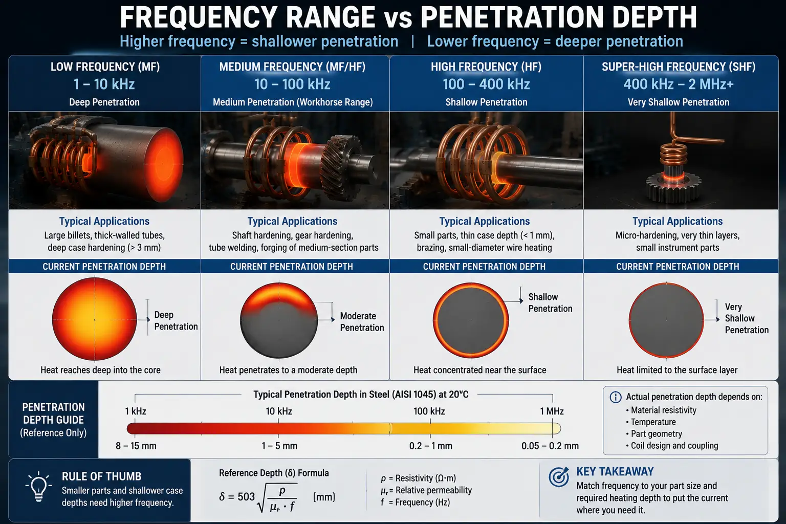
The rule of thumb: smaller parts and shallower case depths need higher frequency. But the real answer comes from calculating the reference depth for your material at the target temperature and matching frequency to put the current where you need it. Guessing wastes a generator. See frequency classification of induction heating equipment for the underlying physics.
2. Power Rating: Nameplate kW vs Real Output
A generator rated at 100 kW does not deliver 100 kW into every load. The nameplate number is maximum output under matched conditions. Run the same generator into a poorly matched coil, at the edge of its frequency range, on a hot day with input voltage sagging—actual output can drop 20–30% before any fault light comes on.
Four things eat the gap between nameplate and real output. Load mismatch: outside the output stage’s impedance range, reflected power rises—100 kW into 50 ohms can become 60 kW into 15 ohms. Frequency-dependent derating: a generator labeled “50 kW, 10–50 kHz” may only deliver full power at 20–40 kHz. Input voltage swings: output follows input; cheaper generators do not regulate. Thermal rollback: at higher duty cycles, internal components heat up and the generator reduces output to protect itself—more on this in section 6.
Size with headroom. If your calculation says 65 kW, buy 80 kW minimum. A generator running at its limit every shift costs more in downtime than the price difference. See how much power you need for induction heating for the calculation method.
3. IGBT, MOSFET, or Vacuum Tube
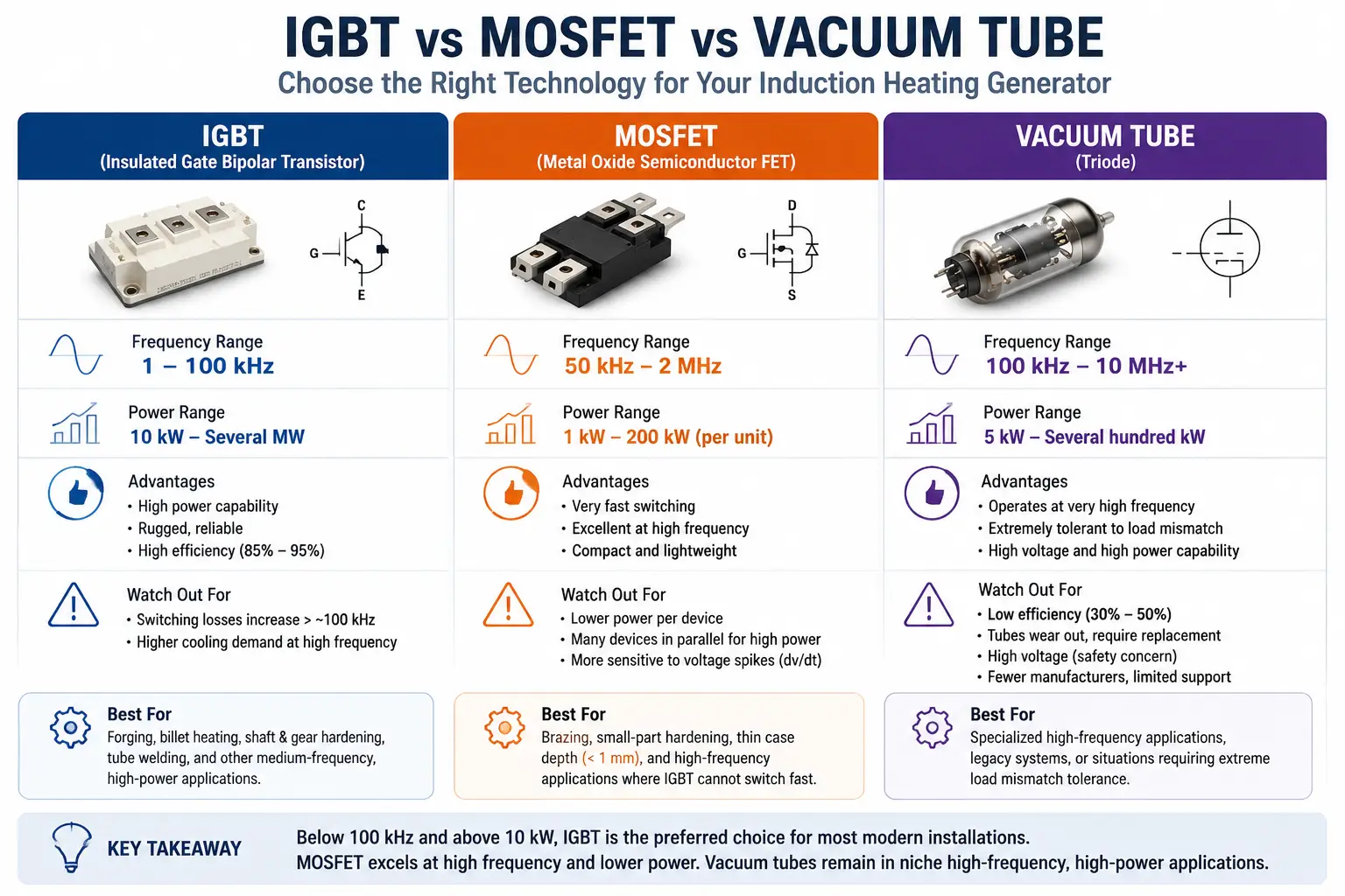
The switching device inside the generator defines its frequency limits, efficiency, robustness, and what happens when something goes wrong. The three technologies sit at different points on a trade-off between switching speed and ruggedness.
4. Resonant Circuit and Load Matching
The generator and coil form a resonant tank circuit. How that tank is arranged—and whether the coil’s impedance falls within the generator’s output range—determines whether power reaches the part or trips a protection circuit.
- Series resonant (voltage-fed). Capacitor in series with the coil. At resonance: minimum impedance, high coil current. Behaves like a voltage source. If load impedance drops, current rises. Needs fast overcurrent protection. Dominates modern IGBT generators—simpler control, lower voltage stress.
- Parallel resonant (current-fed). Capacitor in parallel with the coil. At resonance: high coil voltage. Behaves like a current source—voltage rises if load impedance rises. Handles wide load variations better, useful when coupling changes during heating. For standard applications, series costs less and works. If your part enters and exits the coil mid-cycle, ask the supplier about load transient handling.
- Impedance range. Every output stage has a min and max load impedance it can drive at rated power. Outside that window, circuits trip. Ask for the specified range, not the nominal value. A multi-tap output transformer widens the range of coils a generator can drive without an external matching network.
- — Cable length. Long cables between generator and coil add reactance that shifts the resonant point. Keep the generator close to the work station or factor cable characteristics into the design. A generator and coil specified independently by different people using different assumptions is the single most common commissioning problem. See how induction coils work for coil design fundamentals.
5. Digital vs Analog Control
Analog generators work. A potentiometer sets the power, a meter shows the frequency, an operator adjusts by feel. When the process runs one part, one coil, one temperature, and the same operator for years, analog is enough. Digital adds two capabilities that change the equation when anything varies:
- Repeatable recipes and data logging. Digital stores parameters as numbered recipes. Power, frequency, and faults are recorded over time. Morning shift and night shift load identical settings. Inconsistent hardness in a batch? Check what the generator was doing when those parts ran.
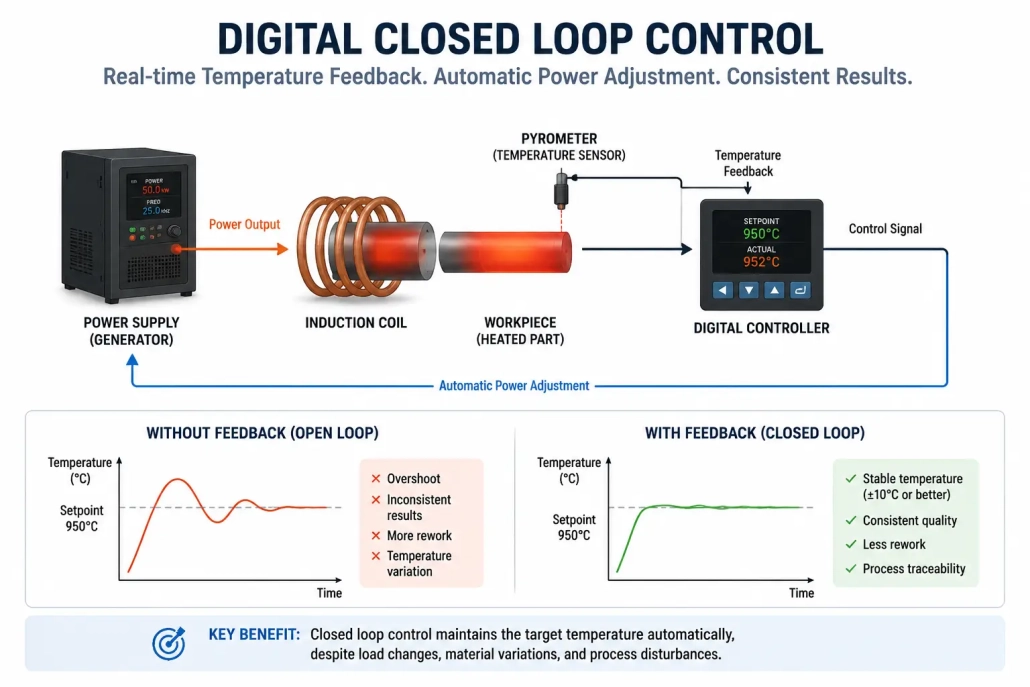
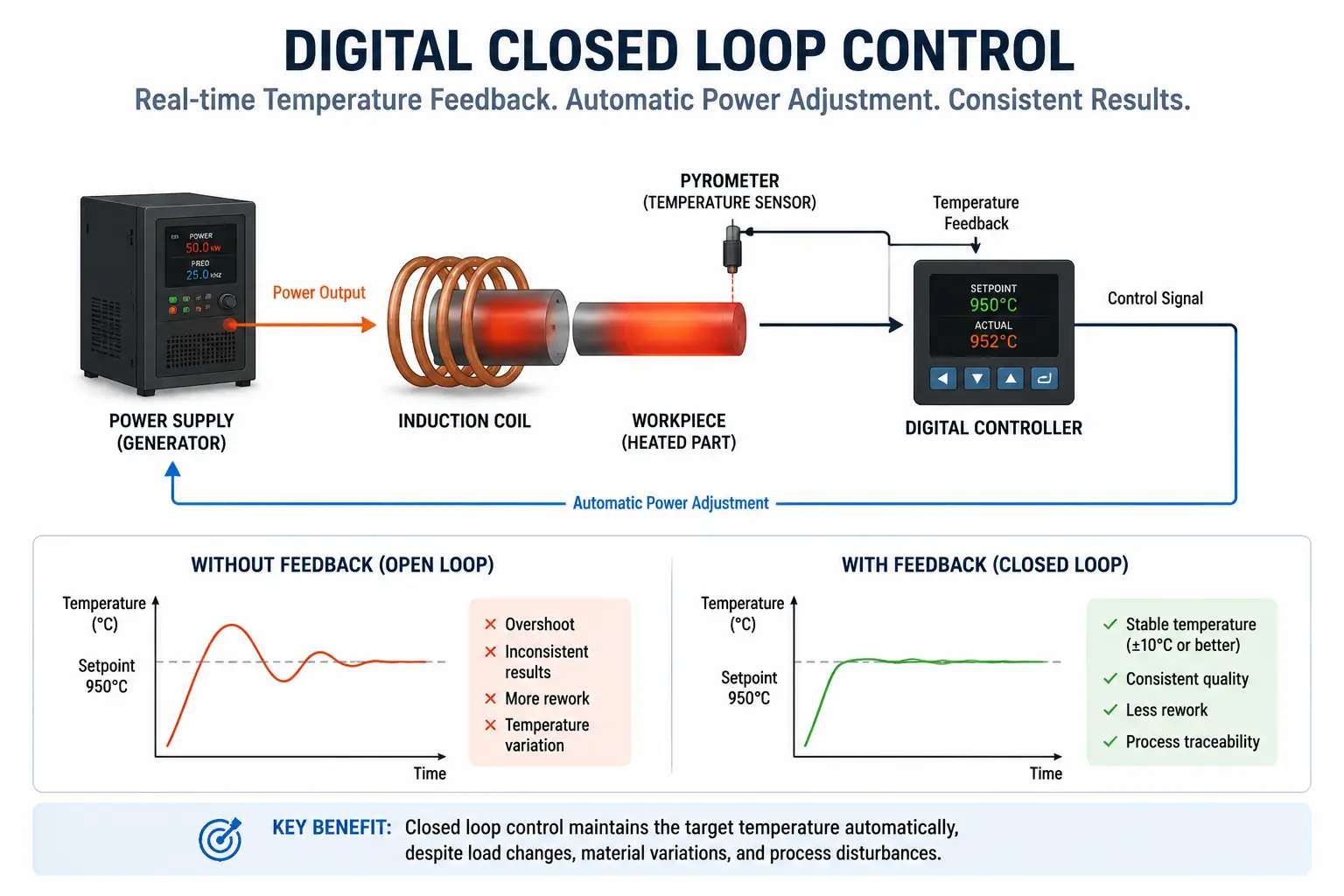
- Closed-loop control. Digital adjusts output in real time based on pyrometer or power sensor feedback. Analog runs open-loop—set a power level and hope the load does not shift. When it does, digital compensates. Analog drifts. If you run multiple parts, care about traceability, or send parts to customers who audit process data, buy digital. See digital induction heating power supply for more.
6. Duty Cycle and Cooling
Duty cycle tells you what percentage of a 10-minute period the generator can run at full power before it must cool. A 50% rating at 100 kW: 5 minutes on, 5 minutes off. Run 7 minutes and internal temperatures outrun the cooling system. Most production lines do not run in neat 10-minute cycles. A forging line heats continuously for hours. A hardening station cycles every 15 seconds. “Continuous” means rated power indefinitely without thermal rollback—but only at specified ambient temperature, water flow, and inlet temperature.
- Water-cooled vs air-cooled. Water handles higher power density and duty cycles. Air is simpler to install but limited to lower power. Above roughly 25–30 kW, water cooling becomes standard. See air-cooled induction heating for the trade-offs.
- Cooling water quality. Hard water deposits scale inside cooling passages. Over months, heat transfer degrades and the generator derates. Closed-loop chillers with treated water eliminate this. Unfiltered tap water is the leading cause of generators that “ran fine for the first year and then started tripping.” See induction heating water cooling.
- Ambient temperature. A generator rated continuous at 25°C may not sustain full power at 40°C in August. The derating curve is in the manual. Ask for it.
Key Takeaway
How to choose an induction heating generator comes down to matching the generator to your coil, your part, and how your line actually runs—not to the highest kW on the spec sheet. The decisions that determine whether it delivers are the ones the catalog buries: impedance range, resonant topology, switching device, duty cycle, and cooling. Ask about them before the purchase order, not during commissioning.
Q: Can I use one generator to drive multiple coils for different parts?
A: Yes, if all coils fall within the generator’s impedance and frequency range. A multi-tap output transformer and digital recipe storage make multi-coil operation practical. Without them, you spend more time re-tuning than heating.
Q: What is the difference between a generator and a power supply?
A: The terms overlap. A power supply converts line power to DC, then to the target AC frequency. A generator is the complete unit: power supply plus controls, protection, output transformer, and cooling in one cabinet, ready to connect to a coil. Most industrial buyers purchase a generator even when the catalog says “power supply.”
Need Help Specifying an Induction Generator?
Tell us your material, dimensions, target temperature, and cycle time. We’ll recommend a generator configuration that fits.


