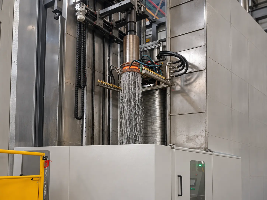
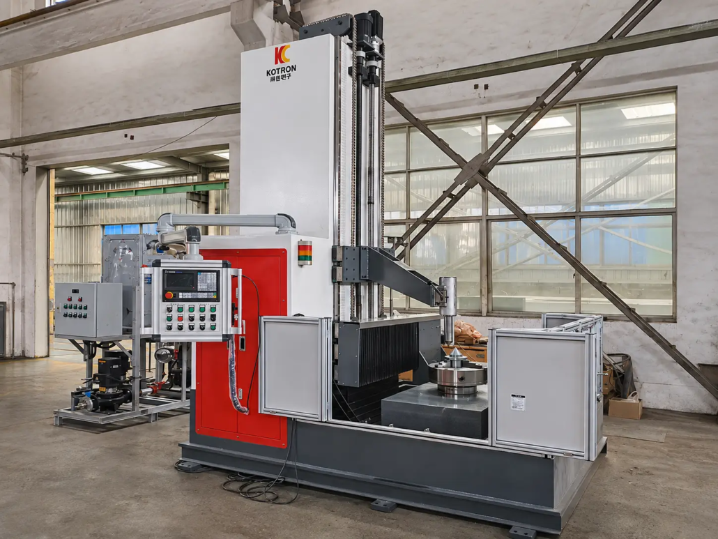
Vertical Induction Hardening Machines for Shaft Hardening, Long Workpieces and Customized Applications
Ⅰ. Vertical Induction Hardening Machines Manufactured by Kechuang
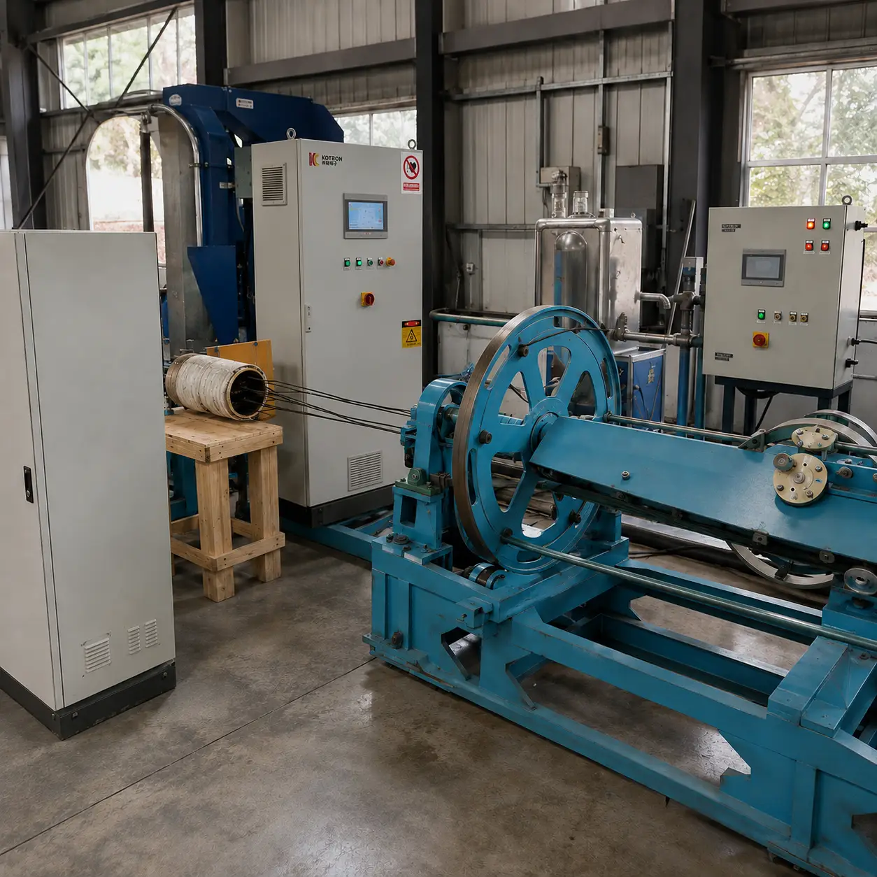
Kechuang has manufactured vertical induction hardening machines with different maximum workpiece clamping lengths. The following 3-meter and 5-meter machines are examples of our equipment design and manufacturing experience.
3-Meter Vertical Induction Hardening Machine
Maximum Workpiece Clamping Length: 3,000 mm
This vertical machine is designed for long shaft workpieces requiring an extended clamping range.
The workpiece can rotate and move axially, while the induction assembly also has axial movement capability. These movement functions can operate independently or in coordination according to the required processing sequence.
This machine demonstrates Kechuang’s experience in designing vertical induction hardening equipment for relatively long shaft components.
5-Meter Vertical Induction Hardening Machine
Maximum Workpiece Clamping Length: 5,000 mm
For longer components, Kechuang has also manufactured a vertical induction hardening machine with a maximum workpiece clamping length of 5,000 mm.
The machine supports workpiece rotation, workpiece axial movement and induction assembly movement. The movement arrangement can be configured to meet the requirements of the heating and scanning process.
This equipment demonstrates our experience in developing larger vertical machine structures for long workpiece induction hardening applications.
Customized Machine Dimensions
The 3-meter and 5-meter machines are examples of equipment already manufactured by Kechuang, not fixed limits on our machine capabilities.
Other workpiece lengths, diameters and weights can be considered. Machine height, clamping range, travel distance and supporting structures are designed according to the actual workpiece.
Maximum workpiece clamping length and effective hardening length are different technical parameters and must be evaluated separately during equipment design.
Ⅱ. Vertical Induction Hardening Machine Design
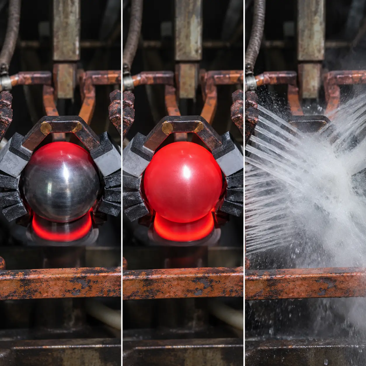
A vertical induction hardening machine integrates workpiece support, mechanical movement, induction heating and quenching into one processing system.
The machine structure depends on the workpiece dimensions, weight, geometry and the areas that need to be hardened. Different applications may require different combinations of workpiece rotation, axial movement and induction assembly movement.
Kechuang designs vertical induction hardening equipment with configurations that can include:
•Vertical workpiece positioning and support
•Customized workpiece clamping and centering mechanisms
•Motorized workpiece rotation
•Adjustable rotation speed and positioning
•Vertical workpiece movement
•Movable induction heating assemblies
•Independent or coordinated movement control
•Customized induction coils and transformer arrangements
•Continuous and segmented scanning configurations
•Spray and immersion quenching systems
•CNC motion control and operating systems
The mechanical structure and heating process are considered together during equipment design. For long shaft workpieces, particular attention is given to support stability, alignment, rotation and the movement required to cover the specified hardening area.
Ⅲ. Workpiece Rotation and Machine Movement Configurations
The rotation and movement arrangement determines how the workpiece and induction heating assembly interact during processing.
Kechuang can design different combinations of workpiece rotation, axial movement and inductor movement rather than restricting the machine to one standard mechanical arrangement.
Workpiece Rotation
The workpiece can rotate during induction heating to achieve circumferential heating around the required surface area.
The rotation mechanism is designed according to workpiece length, diameter, weight and processing requirements. Adjustable rotation speed, positioning and locking functions can also be incorporated where required.
Workpiece Axial Movement
The workpiece can move along its axis during processing. This movement is used in scanning operations where the heating position needs to travel along a specified section of the component.
The travel distance, movement speed and positioning method are configured according to the required hardening area.
Inductor and Transformer Platform Movement
The induction assembly, including its transformer and supporting platform, can also move along the required axis.
This arrangement allows the heating position to travel along the workpiece without relying solely on workpiece movement.
The movement structure and mounting arrangement are designed to suit the induction coil, transformer and machine layout.
Independent and Coordinated Movement
Both the workpiece and induction assembly can be equipped with movement mechanisms.
The two movement systems can operate independently or in coordination. Their travel distance, speed, positioning and operating sequence can be configured according to the required hardening process.
This flexibility allows the machine structure to accommodate different shaft lengths, workpiece geometries and scanning requirements.
Ⅳ. Customized Workpiece Clamping and Positioning Systems
Long workpieces require stable support and accurate positioning during rotation and induction heating.
The clamping and support structure must account for workpiece dimensions, weight, end geometry and potential deflection.
Kechuang can develop workholding arrangements based on the component drawing, including:
•Upper and lower center support
•Adjustable center positioning
•Customized clamping fixtures
•Workpiece alignment mechanisms
•Rotary driving structures
•Positioning and locking mechanisms
•Customized support arrangements for long workpieces
For slender shaft components, alignment and rotational stability are particularly important. The support structure and clamping method must be suitable for the workpiece throughout the heating and quenching cycle.
Ⅴ. Induction Heating and Quenching Processes
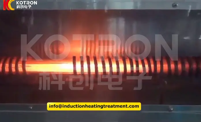
The induction heating system is designed around the material, geometry and required hardened areas of the workpiece.
Kechuang’s vertical induction hardening equipment supports several heating and quenching arrangements.
Continuous Immersion Quenching
Continuous immersion quenching is used for applications where the heated workpiece section enters the quenching medium according to the specified processing sequence.
The immersion arrangement, movement sequence and quenching conditions are designed according to the workpiece and hardening requirements.
Spray Quenching
Spray quenching delivers quenching liquid to the heated area through a dedicated spray arrangement.
The spray position, quenching structure and liquid supply are configured to match the induction coil and workpiece geometry.
Segmented Scanning Hardening
Segmented scanning hardening is suitable for components requiring multiple hardened sections along their length.
The scanning positions, travel distances and processing sequence can be programmed according to the required hardened areas.
Fixed-Position Heating and Quenching
For localized hardening at a specific position, the machine can perform fixed-position induction heating followed by quenching.
The heating position, heating time and quenching sequence are determined according to the component and process requirements.
Customized Induction Coils and Heating Systems
The induction coil is designed according to the workpiece geometry and required heating pattern.
Important design considerations include:
•Coil geometry and dimensions
•Coil-to-workpiece clearance
•Heating area and hardened section
•Coil mounting and adjustment
•Transformer and inductor arrangement
•Heating power and operating frequency
•Quenching system integration
The induction heating and quenching systems are evaluated together to achieve the required surface hardening results.
Ⅵ. CNC Motion Control and Machine Automation
The control system coordinates workpiece rotation, mechanical movement and the induction hardening cycle.
Depending on the machine configuration, control functions can include:
•Workpiece rotation and speed adjustment
•Workpiece axial movement
•Inductor platform movement
•Independent axis operation
•Coordinated movement sequences
•Scanning distance and speed control
•Positioning and stopping
•Induction heating parameter control
•Quenching sequence control
•Manual and automatic operating modes
•Equipment status monitoring and protection
The CNC system, electrical configuration and automation level are selected according to the required machine functions.
For projects involving multiple moving assemblies, the control system can coordinate the relevant movements and processing sequences to achieve the required operating cycle.
Ⅶ. Applications for Shaft Components and Other Workpieces
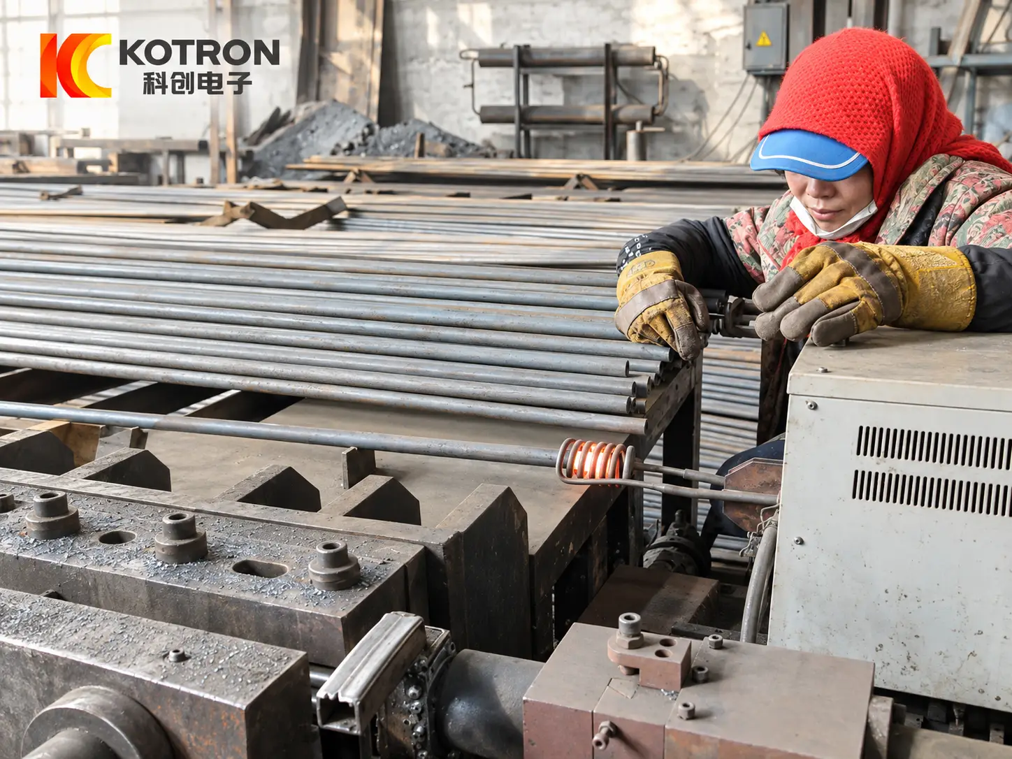
Vertical induction hardening machines are suitable for workpieces that require vertical positioning, controlled rotation or axial scanning during surface hardening.
Potential applications include:
•Drive shafts
•Industrial machine shafts
•Spindle shafts
•Stepped shafts
•Other elongated steel components requiring localized induction hardening
Different workpieces may require different clamping methods, rotation arrangements, induction coils and scanning configurations.
The appropriate machine structure depends on the component dimensions, material, hardened area and production requirements. Customers can provide workpiece drawings or sample photographs for an initial equipment and process assessment.
Ⅷ. Technical Parameters and Customization Options
There is no single machine configuration suitable for every shaft or production application.
During project evaluation, Kechuang considers the following technical parameters:
| Parameter | Design Considerations |
|---|---|
| Maximum workpiece clamping length | Overall workpiece length and clamping arrangement |
| Workpiece diameter | Component geometry and support structure |
| Workpiece weight | Loading, support and rotation requirements |
| Effective hardening length | Required hardened area |
| Workpiece rotation | Rotation speed, positioning and movement sequence |
| Workpiece movement | Axial travel and operating speed |
| Inductor movement | Travel distance and positioning |
| Induction coil | Coil geometry and heating area |
| Quenching system | Immersion or spray quenching |
| Control system | Movement control and process coordination |
The 3,000 mm and 5,000 mm maximum clamping length configurations shown on this page are examples of machines already manufactured by Kechuang. Other dimensions and mechanical arrangements can be developed for specific projects.
Ⅸ. Frequently Asked Questions
Click a question to expand the answer.
What is a vertical induction hardening machine used for?
It is used for localized induction heating and quenching of vertically positioned workpieces. Shaft components are a common application, particularly when workpiece rotation or axial scanning is required.
What is the maximum workpiece clamping length of your machines?
Kechuang has manufactured vertical machines with maximum workpiece clamping lengths of 3,000 mm and 5,000 mm. Other lengths can be evaluated and customized according to the workpiece and project requirements.
Can you manufacture machines for workpieces longer than 5 meters?
Yes. Different machine lengths can be considered. The required frame dimensions, clamping structure, support arrangement and movement range are evaluated according to the workpiece and processing requirements.
Can both the workpiece and induction assembly move?
Yes. Both can have axial movement capabilities. Their movement systems can operate independently or in coordination according to the required processing sequence.
What induction hardening processes can the machines perform?
The equipment supports continuous immersion quenching, spray quenching, segmented scanning hardening and fixed-position heating and quenching. The appropriate configuration is selected according to the workpiece and process requirements.
Can the machine be customized for different workpiece shapes and rotation requirements?
Yes. Workpiece clamping, support, rotation and positioning mechanisms can be designed around the component geometry and required processing method.
Ⅹ. Request a Customized Vertical Induction Hardening Machine
Looking for a vertical induction hardening machine for your workpiece?
Simply send us a workpiece drawing or a few photos, along with a brief description of your application. If available, you can also share the material, workpiece dimensions and required hardening area.
Our engineering team will review your requirements and discuss a suitable machine structure, movement arrangement and induction hardening solution.
Even if your technical requirements are not fully defined, feel free to contact us. We can help you explore the right equipment configuration.
Request a Customized Vertical Induction Hardening Machine
Send us your workpiece drawing or photos and we will discuss the appropriate machine structure and induction hardening solution for your application.