Air-Cooled vs. Water-Cooled Induction Heating Systems: A Practical Selection Guide
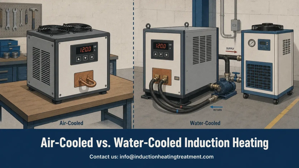
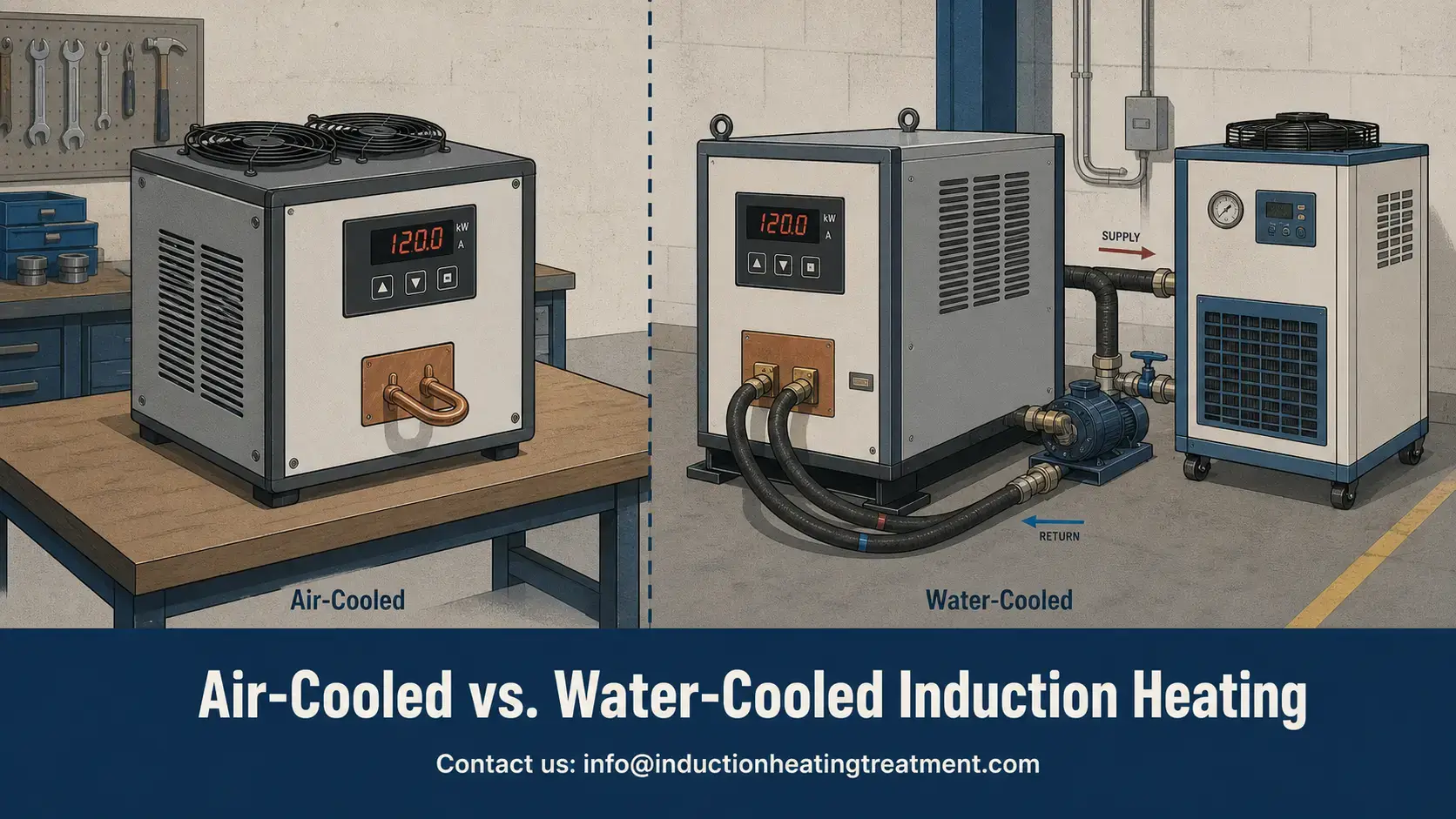
Choosing between air-cooled vs water-cooled induction heating is not about which method is better. It is about which method matches your power level, duty cycle, shop environment, and tolerance for infrastructure. Pick wrong, and you either pay for plumbing you do not need or watch your machine trip on thermal overload in the middle of a production run. This guide walks through the decision in six steps—from a 30-second filter to a full system layout.
1. The One-Question Filter
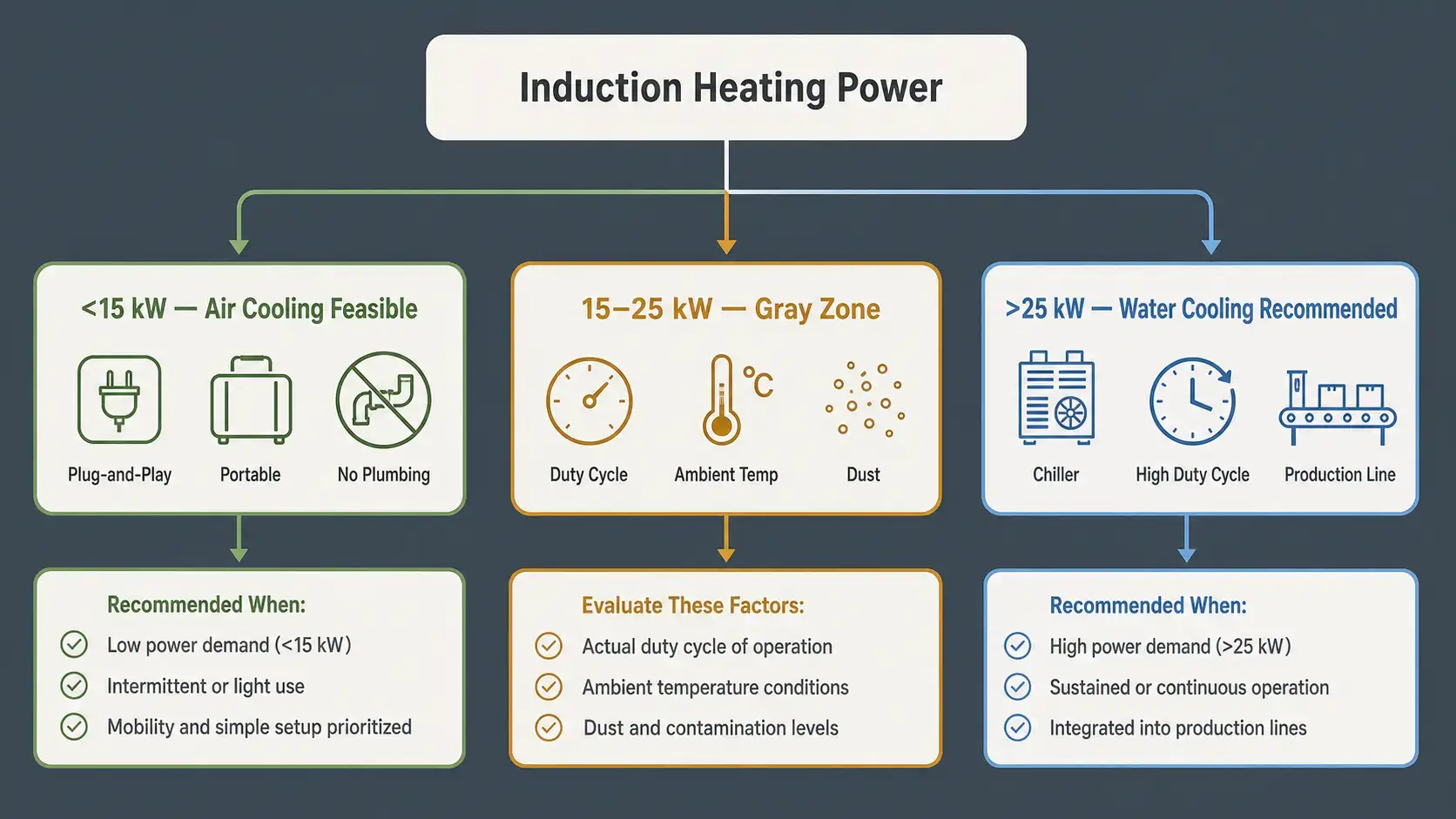
Start with one question: how much power does your induction heating process actually need? If you do not yet have a firm power number, see our guide on how much power you need for induction heating. Once you have it, the cooling decision follows a predictable pattern:
| Your Power | Most Likely Answer |
|---|---|
| < 15 kW | Air cooling — simple, portable, sufficient |
| 15–25 kW | Depends on duty cycle, ambient, and dust |
| > 25 kW | Water cooling — air cannot keep up |
This is the starting point, not the final answer. A 12 kW machine running continuous brazing in a 40°C foundry may still need water cooling. A 20 kW machine doing occasional bearing heating in an air-conditioned shop is fine on air. The next section gives you the full picture.
2. Air vs. Water vs. Hybrid: Decision Matrix
| Factor | Air-Cooled | Water-Cooled | Hybrid (Coil Water + Cabinet Air) |
|---|---|---|---|
| Power range | ≤ 25 kW | 5–500+ kW | 15–50 kW |
| Duty cycle tolerance | Intermittent to medium | Continuous | Medium to high |
| Ambient temperature limit | Derates above 30–35°C | Chiller handles ambient swings | Cabinet side still derates in heat |
| Installation complexity | Plug and play | Chiller, pump, piping, reservoir | Half the plumbing of full water cooling |
| Space requirement | Ventilation clearance 200–300 mm | Chiller footprint + piping + pump | Smaller than full water, larger than pure air |
| Maintenance burden | Monthly filter cleaning, quarterly heat sink inspection | Water quality monitoring, leak checks, annual coolant change | Filter cleaning + coil water loop maintenance |
| Noise | 60–75 dB at full load | 50–65 dB (chiller can be placed remotely) | Lower fan count than full air |
| Portability | Excellent | Tethered to water infrastructure | Moderate |
| Upfront cost | Lowest | Highest | Middle |
| Operating cost driver | Fan electricity, filters | Chiller power, water treatment | Fan electricity + reduced water volume |
Do not look for the column with the most green. Look for the column where the limitations matter least for your process. A maintenance shop moving its heater between workstations values portability—air cooling wins. A three-shift production line values thermal stability—water cooling is the only answer. For detailed engineering on each method, see our dedicated guides on water-cooled systems and air-cooled induction heating.
3. Heat Load Calculation
Before you compare equipment prices, calculate how much waste heat your process produces. A modern IGBT-based induction power supply loses roughly 20–25% of its rated output power as waste heat. The formula:
Cooling kW = Rated Power × 20–25%
From there, required flow rate follows from the allowable temperature rise across the equipment, typically ΔT = 5–8°C:
Flow (L/min) = (Cooling kW × 60) ÷ (4.18 × ΔT)
Once you have the cooling load, add a 20% safety margin before selecting a chiller model. For a complete worked example with real numbers, sizing tables across common power levels, and chiller selection guidance, see our water cooling system guide.
4. System Integration: Layout and Space Planning
Choosing the cooling method is one thing. Making it work in a real production space—with existing utilities, limited floor space, and neighboring equipment—is where good planning pays off.
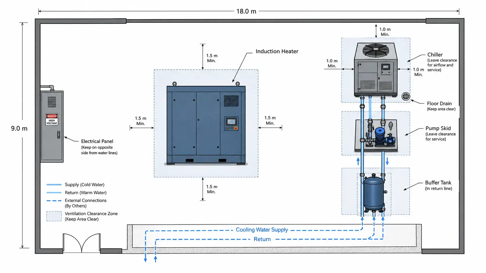
Water-cooled layout. A water-cooled installation includes five physical elements: induction heater, chiller, pump, buffer tank, and piping.
— Keep the chiller within 10–15 meters of the induction heater. Longer runs increase pump head, add heat gain, and raise installation cost. If the chiller must be farther, insulate the supply line and spec the pump accordingly.
— Maintain at least 1 meter clearance around the chiller on intake and exhaust sides. A chiller in a corner with the exhaust facing a wall loses 30–50% of its rated capacity.
— Separate water and electricity. Cooling lines should not run above electrical panels or exposed busbars. If piping must cross electrical areas, install drip trays.
— Include a floor drain near the chiller and buffer tank for coolant changes, filter service, and the occasional hose failure.
— Mount the pump below the reservoir level for positive suction head, eliminating the most common cause of pump cavitation.
Air-cooled layout.
— Ventilation clearance is not optional. The manual will specify minimum intake and exhaust distances—typically 200–300 mm. Ignore it, and the machine recirculates hot exhaust in a feedback loop that ends with a thermal trip.
— Do not place the machine near a heat source—furnace, welding cell, direct sunlight. Inlet air at 40°C instead of 25°C sharply reduces cooling capacity.
— Stagger multi-machine layouts so no machine’s exhaust faces another machine’s intake.
Hybrid layout. In a hybrid setup, the coil runs on a dedicated water loop while the cabinet is air-cooled. The two circuits are independent: the cabinet follows air-cooled spacing rules, the coil circuit follows water-cooled layout rules. This is most practical when the coil runs hot (multi-turn, close to workpiece at 850°C) but the power electronics are moderate (20–30 kW).
5. Cost Drivers: What Actually Moves the Budget
Cooling system cost does not come from a catalog price. It comes from a set of variables that interact. Here is what actually matters—and what does not.
— Duty cycle. For air-cooled, high duty cycle forces you toward the upper power limit or into derating—the cost is lost throughput. For water-cooled, high duty cycle increases chiller electricity, but a properly sized chiller handles it. Air cooling’s penalty is production lost to thermal limits; water cooling’s penalty is higher operating cost.
— Water quality at your site. Hard municipal water (TDS > 200 ppm) requires either a closed-loop system with deionized water or a treatment system—adding 15–30% to cooling infrastructure cost. Soft water eliminates this variable. Air-cooled systems are unaffected.
— Ambient temperature. Hot shops degrade both methods—air cooling hits a hard thermal wall (derating or shutdown), water cooling sees higher chiller power consumption. The difference: water cooling degrades gradually; air cooling stops.
— Distance between equipment and chiller. Every meter of piping adds material and pump sizing cost. This variable does not exist for air-cooled systems.
— Maintenance labor. Air cooling needs frequent, low-skill maintenance (filters, fan checks). Water cooling needs less frequent, more skilled work (chemistry testing, seal replacement). If your team already maintains water-cooled CNCs or welders, adding one more water loop is incremental. If not, the learning curve is real.
— Local electricity rates. A chiller draws 25–35% of the waste heat it removes. At $0.08/kWh this is modest. At $0.25/kWh over three shifts and 250 production days, it becomes a significant line item. Air cooling pays fan power only—a fraction of chiller power—but at higher power levels it cannot remove the heat at all.
What does not drive cost: the induction heater itself (air vs water purchase price is within 10–15%), coolant consumables (< $100/year), and pump electricity (2–3 kW—rounding error compared to heater and chiller).
6. When a Hybrid Cooling Approach Makes Sense
Most induction systems cool everything with one method. In the 15–50 kW range, there is a third option: water-cool the coil, air-cool the cabinet.
| Scenario | Why Hybrid Works |
|---|---|
| 20–30 kW, compact coil heating at 900°C | Coil needs liquid cooling; cabinet waste heat (5–7 kW) is within air range |
| No existing chiller infrastructure | A small dedicated chiller for the coil only is cheaper than full system water cooling |
| Intermittent production (50–60% duty cycle) | Cabinet fans recover between cycles; coil water loop prevents mid-cycle coil overheating |
| Machine needs periodic relocation | Smaller water loop = fewer connections to break and remake |
| Scenario | Why Not |
|---|---|
| Power above 50 kW | Cabinet waste heat exceeds air cooling limits regardless of coil configuration |
| Continuous duty, hot environment | Cabinet fans will saturate; full water cooling is the only reliable option |
| Cabinet already designed for water cooling | Water-cooled heat sinks lack fin geometry for air—not retrofittable |
Key Takeaway
Air-cooled vs water-cooled induction heating is a thermal reality check, not a feature comparison. The decision starts with power level: below 15 kW, air cooling handles it with simplicity and portability. Above 25 kW, water cooling is the only practical path. In between, duty cycle, ambient temperature, and water quality decide. Do the heat load calculation before comparing prices—a machine that cannot remove its own waste heat is a future downtime report. For detailed engineering on each method, our guides on air-cooled induction heating and water-cooled systems cover components, specifications, and maintenance procedures.
FAQ
Q: What is the most common cooling system mistake?
A: Undersizing the chiller. Engineers calculate the waste heat correctly, skip the safety margin, and spec the exact size. Then summer arrives, the shop ambient climbs 10 degrees, and the chiller cannot hold setpoint. Add 20% to your calculated cooling load before selecting a chiller. The incremental cost is small; the cost of thermal trips during a production run is not.
Q: How do I quickly decide between air cooling and water cooling?
A: Start with power. Below 15 kW, air cooling is usually sufficient. Above 25 kW, water cooling is required. Between 15 and 25 kW, factor in your duty cycle and shop environment. Air-conditioned shop with intermittent use—air may work. Hot, dusty, or continuous operation—go water even at these levels. The full decision matrix in Section 2 gives the complete comparison.
Not Sure Which Cooling Approach Fits Your Process?
Tell us your target power level, expected duty cycle, shop environment, and available utilities. We’ll help you evaluate air-cooled, water-cooled, and hybrid options for your specific application.