
Induction Power Supply Shuts Down With No Alarm: A Field Troubleshooting Case
An induction power supply that starts normally but shuts down as power rises can be difficult to diagnose, especially when no clear fault alarm appears.
A field troubleshooting record we reviewed described this problem on an 800 kW IGBT series-resonant induction power supply used for an aluminum melting furnace.
The equipment had previously operated normally. Later, it began stopping automatically as output power increased. It could be restarted immediately, but raising the power reproduced the same fault.
The problem remained unresolved for more than a month.
The eventual fault source was traced to a 750 V / 10 V line-voltage sensing transformer (ST1/ST2) that had previously been replaced by the user.
The value of this case is not simply the failed component. The troubleshooting process shows why operating history and changes made before a fault appeared can be as important as electrical measurements.
1. The Fault: Normal Startup, Shutdown at Higher Power
The symptoms were consistent:
— startup was normal
— power increased normally at first
— the power supply stopped automatically above a certain operating level
— no clear fault alarm appeared
— restart was normal
— increasing the power reproduced the shutdown
Because the furnace had previously operated normally at high power, a basic installation problem seemed less likely.
The absence of an alarm made the fault more difficult to classify. There was no obvious overcurrent, overvoltage or other protection message pointing directly to one part of the system.
2. Why the Control Side Became Suspect
The control board contained A and B inverter-control channels, although only the A output was used in normal production.
During troubleshooting, both channels were enabled.
When the shutdown occurred, the unused B-channel control stopped as well.
This suggested that the problem might not be limited to the active A-channel power stage. Attention therefore shifted toward a disturbance affecting a shared control or measurement path.
Interference was still only a working diagnosis at this point.
One possible source was the furnace coil. If coil-to-ground insulation had deteriorated, electrical discharge at higher voltage could potentially disturb the control system.
The next test was intended to see whether the shutdown followed a repeatable coil-voltage condition.
3. Two Load Tests Narrowed the Search
The furnace was tested under two different load conditions:
The shutdown occurred at substantially different coil voltages:
— approximately 1500 V with the empty furnace
— approximately 1000 V with the cold crucible
The reported current was approximately 1500 A in both tests.
For this particular case, the result made a simple fixed coil-voltage-triggered discharge less consistent with the observed fault.
It did not prove that the furnace-coil insulation was perfect. Nor should different shutdown voltages be treated as a universal method for ruling out an insulation problem.
They were simply enough to move this investigation toward another possible path into the control system.
Note: The voltage, current and power values above are the operating values recorded in the original troubleshooting process. In a resonant induction power system, they should not be interpreted using a simple DC P = V × I relationship.
4. Tracing the Fault Through the Measurement Path
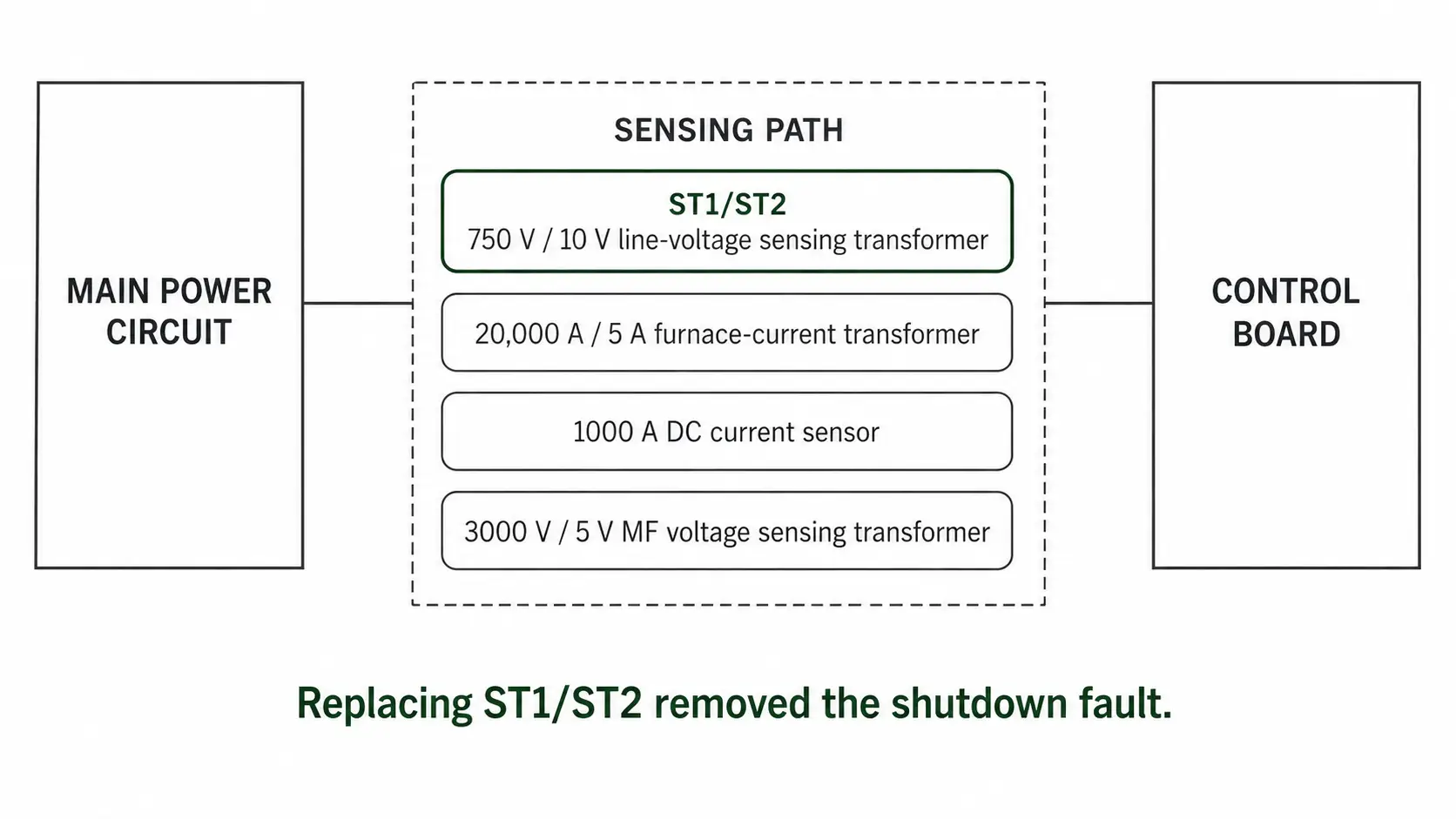
The control system received several measurements from the main electrical circuit. The associated sensing devices included:
| Measurement | Sensing Device |
|---|---|
| Line voltage | 750 V / 10 V line-voltage sensing transformer |
| Furnace current | 20,000 A / 5 A furnace-current transformer |
| DC current | 1000 A DC current sensor |
| Medium-frequency voltage | 3000 V / 5 V medium-frequency voltage sensing transformer |
These devices form part of the interface between a high-power electrical environment and the control electronics.
The working diagnosis was that one of the sensing paths might have deteriorated enough for interference from the main circuit to affect the controller as the operating load increased.
One possible approach would have been to disconnect the measurement channels one by one.
On an 800 kW power supply, however, removing feedback signals can also change how the controller limits and regulates the system. It is not a suitable trial-and-error procedure without detailed knowledge of the machine’s control program and safe operating limits.
A substitution approach was therefore used.
After replacing the 750 V / 10 V ST1/ST2 sensing transformer, the abnormal shutdown disappeared.
The power supply could again increase output without reproducing the fault.
That substitution identified ST1/ST2 as the fault source.
The exact internal failure mechanism was not confirmed by laboratory testing. The working diagnosis was that the component’s isolation or resistance to electrical interference had deteriorated enough to disturb the control circuit at higher operating load.
5. What Had Changed Before the Fault?
The maintenance history later provided an important clue.
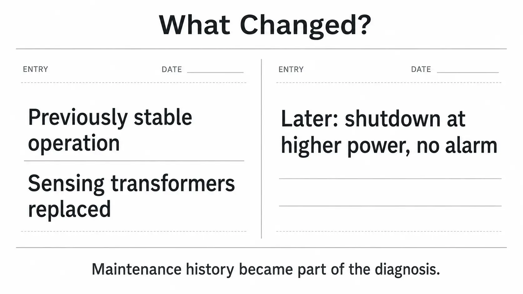
One of the original line-voltage sensing transformers had previously failed. The user then obtained replacement components from another supplier and replaced both original units.
The furnace continued operating for some time after the replacement, so the connection between the replacement parts and the later shutdown was not obvious at first.
That history changed how the fault was understood.
The problematic sensing transformer was no longer part of the original configuration that had previously operated reliably.
It also shows why a replacement component should not be selected only because the visible ratio appears to match.
A device marked 750 V / 10 V still needs to meet the electrical and insulation requirements of the circuit in which it is used.
This case does not establish exactly which internal characteristic of the replacement component had deteriorated. What the troubleshooting result does establish is that replacing ST1/ST2 removed the shutdown.
6. What This Case Actually Tells Us
The wrong conclusion would be:
An induction power supply that shuts down without an alarm probably has a bad voltage sensing transformer.
One case cannot support that rule.
The more useful lesson is about troubleshooting order.
When equipment has operated normally for a long period and then develops an unusual fault, ask early:
— Was any component replaced before the problem appeared?
— Were parameters, wiring or machine settings changed?
— Was anything changed on the furnace, coil, cooling system or production process?
— Was there an unusual sound, smell, discharge or previous alarm?
Then compare those changes with the fault pattern.
In this case, the useful sequence was:
01 previously stable equipment
02 shutdown only as output increased
03 no clear alarm
04 both control channels were affected
05 different load conditions produced different shutdown voltages
06 attention shifted toward the measurement / control path
07 ST1/ST2 was replaced
08 the fault disappeared
09 maintenance history revealed that the sensing transformers had already been replaced
A high-power symptom also does not automatically mean that a large power component such as an IGBT module has failed.
The source of a shutdown may be a much smaller part of the sensing, feedback or control chain.
At the same time, feedback and protection circuits on a high-power induction system should not be bypassed casually during troubleshooting. Tests that alter control or protection functions require knowledge of the specific machine.
Final Takeaway
The failed component in this case was small compared with an 800 kW induction power supply. Its effect on production was not.
The most useful lesson is broader than ST1/ST2:
Maintenance history should be treated as diagnostic data, not background information.
When a previously stable induction power supply suddenly behaves differently, knowing what was replaced, adjusted or moved before the fault appeared may narrow the search faster than starting with the largest power components.
Frequently Asked Questions
Click a question to expand the answer.
+ Why does an induction power supply shut down with no alarm?
A shutdown without a clear fault alarm often points to the sensing or feedback path rather than a hard protection trip. Interference from the main circuit can disturb the controller as the load rises, without triggering an overcurrent or overvoltage message.
+ Does a no-alarm shutdown always mean a bad voltage sensing transformer?
No. This case traced to a sensing transformer, but that does not make it a general rule. Use it as a reminder to check the measurement path, not as a shortcut to a conclusion.
+ Can I disconnect feedback signals one by one to find the fault?
Not without detailed knowledge of the control program and safe operating limits. On a high-power supply, removing feedback changes how the controller limits and regulates the system. A substitution approach is safer.
+ What should I check first when a previously stable power supply starts shutting down?
Ask what changed before the fault appeared — a replaced component, adjusted parameter, rewiring, or a change to the furnace, coil or cooling system. Maintenance history is diagnostic data, not background.
Need Help Diagnosing an Induction Power Supply Fault?
Send your operating symptoms and maintenance history. We will help you narrow down the cause before the next shutdown.


